Shower head and cvd apparatus using the same

a shower head and cvd technology, applied in the direction of electric discharge tubes, coatings, chemical vapor deposition coatings, etc., can solve the problems of showerheads that are not suitable for forming gas species films, increase the production cost of plate sections, etc., and achieve high efficiency forming films, efficient dissociation, and substantial increase in ionization efficiency

Inactive Publication Date: 2008-08-21
ORBOTECH LT SOLAR
View PDF13 Cites 133 Cited by
  • Summary
  • Abstract
  • Description
  • Claims
  • Application Information

AI Technical Summary

Benefits of technology

[0037]a plurality of gas diffusion grooves are formed in a plate section of the main body part, which faces the workpiece. With this structure, gasses, which are hard to be ionized, can be efficiently dissociated, so that film-forming efficiency of the CVD apparatus can be improved.
[0038]The showerhead of the present invention is constituted by the shower plate having the gas diffusion holes and the porous plate, or by the porous main body part having the gas diffusion grooves, so ionization efficiency of the showerhead can be substantially increased. By supplying the gas through the porous member, the gas can be uniformly supplied. Therefore, even if gas species, which are hard to be ionized, are used, the showerhead is capable of highly efficiently forming the film. Further, by using the porous plate or the porous main body part, the showerhead can be easily produced, a production cost of the showerhead can be reduced, and a production time thereof can be shortened.

Problems solved by technology

In the showerhead having the plate section, a large number (several hundreds to several thousands) of the gas diffusion holes must be formed, so a production cost of the plate section must be increased.
However, in the showerhead made of the porous ceramic, the gas cannot be efficiently ionized, so the showerhead is not suitable for forming a film with gas species which are hard to be ionized, e.g., silicon nitride (SiNx).

Method used


Image

  • Shower head and cvd apparatus using the same
  • Shower head and cvd apparatus using the same
  • Shower head and cvd apparatus using the same

Examples


first embodiment

Showerhead of First Embodiment

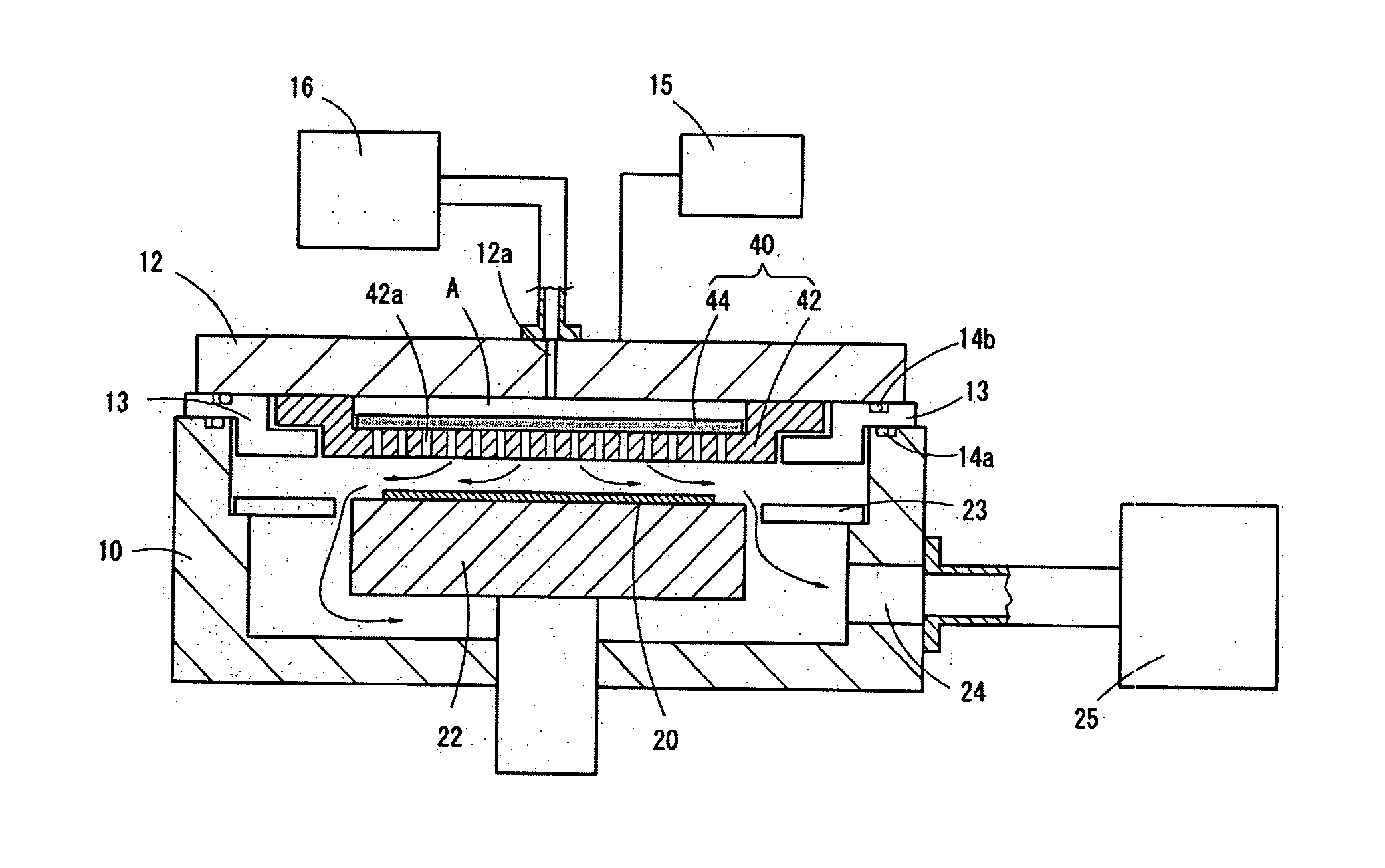
[0066]The most characteristic point of the CVD apparatus is the showerhead 40 facing the workpiece 20.

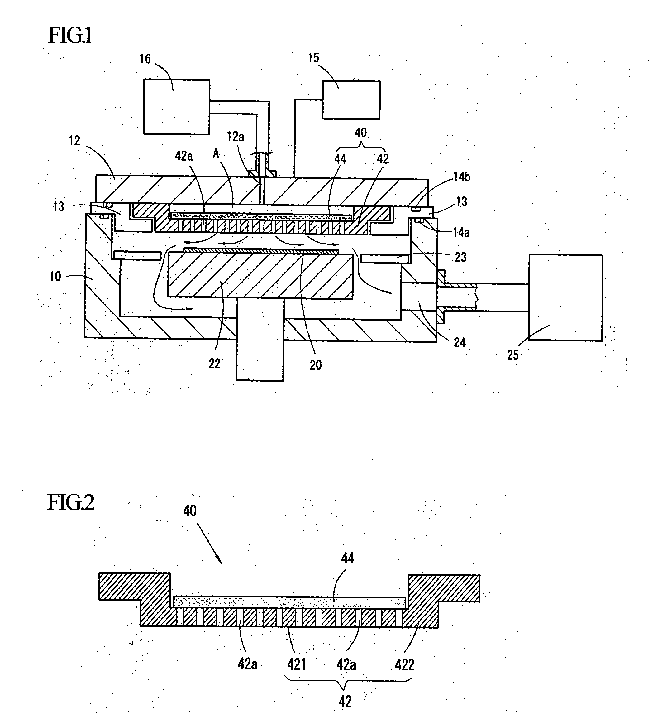
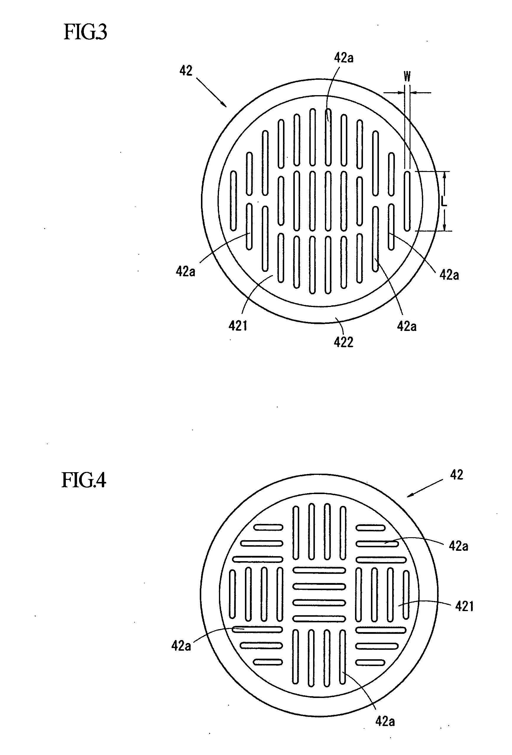
[0067]FIG. 2 is an enlarged sectional view of the showerhead 40. The shower plate 42 of the showerhead 40 comprises: a plate section 421, which is formed into a flat plate and disposed to face the workpiece 20; and a flange section 422 extended from an outer edge of the plate section 421. The flange section 422 is used for attaching the showerhead 40 to the electrode 12. The shower plate 42 is made of an electric conductive material, e.g., metal.

[0068]As described above, a plurality of the gas diffusion holes 42a penetrate the plate section 421 in the thickness direction. Ratio of the width W of the gas diffusion hole 42a to the depth H thereof is 1:1-1:10. By making the depth H equal to or greater than the width W, ionizing the gas in the gas diffusion layer 42a can be accelerated and film-forming efficiency can be improved. The depth H and the width W...

second embodiment

Showerhead of Second Embodiment

[0087]In the showerhead of a second embodiment, a metal plate 50 is used instead of the porous plate 44.

[0088]The showerhead 40 having the metal plate 50 is shown in FIGS. 9, 10A and 10B. FIG. 9 is a sectional view of the showerhead 40. In the present embodiment, the metal plate 50 having gas holes 51 is set on the plate section 421 of the shower plate 42, which has the gas diffusion holes 42a as well as the first embodiment.

[0089]Each of the gas holes 51 is constituted by: a vertical hole 52 penetrating through the metal plate 50 in the thickness direction; and communication grooves 54 being formed in a lower surface of the metal plate 50 so as to communicate with the gas diffusion holes 42a.

[0090]The vertical holes 52 are arranged so as not to correspond to the gas diffusion holes 42a. In another words, each of the vertical holes 52 is located between the adjacent gas diffusion holes 42a and covered with the plate section 421 of the shower plate 42....

third embodiment

Showerhead of Third Embodiment

[0097]The showerhead of the third embodiment is shown in FIGS. 11A and 11B. A showerhead 60 of the present embodiment is characterized by a porous main body made of a sintered metal.

[0098]FIG. 11A is a sectional view of the showerhead 60. The showerhead 60 comprises: a plate section 601; and a flange section 602, which is extended from an outer edge of the plate section 601. The flange section 602 is attached to the electrode 12, and a gas introduction space is formed on the rear side of the plate section 601.

[0099]A plurality of gas diffusion grooves 60a are formed in a surface of the plate section 601, which faces the workpiece 20. The gas diffusion holes 42a of the shower plate 42 are through-holes penetrating the plate section 421 in the thickness direction; the gas diffusion grooves 60a are grooves whose upper parts are closed. In the above described showerhead 40, the shower plate 42 and the porous plate 44 are combined so as to close the upper pa...


PUM

PropertyMeasurementUnit
inner diametersaaaaaaaaaa
widthaaaaaaaaaa
distancesaaaaaaaaaa

Abstract

The showerhead for a CVD apparatus can be easily produced and is capable of forming a film efficiently. The showerhead comprises: a shower plate being made of a metal; and a porous plate contacting a rear face of the shower plate. A plurality of gas diffusion holes are formed in a plate section of the shower plate, which faces a workpiece, and penetrate the plate section in the thickness direction, and the porous plate covers all of the gas diffusion holes.

Description

BACKGROUND OF THE INVENTION[0001]The present invention relates to a showerhead and a CVD (Chemical Vapor Deposition) apparatus using the showerhead.[0002]In a typical plasma CVD apparatus, a process gas for forming a film is supplied into a chamber, and then RF (Radio Frequency) waves are applied to a showerhead so as to generate plasma and ionize the gas, so that the film is formed on a surface of a workpiece, which is disposed to face the shower head.[0003]The showerhead of the CVD apparatus is used for efficiently ionizing the gas and uniformly forming the film on the surface of the workpiece. Various of types of showerheads have been provided. A typical showerhead has a plate section, which faces the workpiece and in which gas diffusion holes are formed, and the gas is sprayed from the gas diffusion holes toward the workpiece, so that the gas is dissociated and the film is formed thereon. Further, Japanese Patent Gazettes No. 2003-28142 and No. 2003-7682 disclose showerheads, wh...

Claims


Application Information

Patent Timeline
Patent Type & Authority Applications(United States)
IPC IPC(8): C23C16/00C23C16/34
CPCC23C16/45565H01J37/3244H01J37/32091C23C16/5096
Inventor TOSHIMA, MASATO
Owner ORBOTECH LT SOLAR
Why Eureka
Try Eureka