High conductivity ceramic foam cold plate

a ceramic foam and high conductivity technology, applied in the field of cold plate methods and apparatuses, can solve the problems of unacceptably high pressure drop, reduced cooling reduced cooling efficiency of cold plate, so as to maximize the thermal performance of cold plate, improve cooling, and mitigate the effect of pressure drop change through the cold pla

Active Publication Date: 2008-08-21
THE BOEING CO
View PDF5 Cites 37 Cited by
  • Summary
  • Abstract
  • Description
  • Claims
  • Application Information

AI Technical Summary

Benefits of technology

[0014]One advantage of the present invention includes improved cooling compared to plate fin and aluminum foam cold plates.
[0015]Another advantage of the present invention includes maximizing thermal performance of a cold plate while mitigating change in pressure drop through the cold plate.
[0016]Further aspects of the method and apparatus are disclosed herein. Other features and advantages of the present

Problems solved by technology

However, surface area densities for finned core stock and metal foams are generally limited to approximately 1000 ft2/ft3.
This is chiefly because surface area densities significantly larger than this value result in unacceptably high pressure drop as the coolant flows through the cold plate.
High pressure drop translates into a system penalty in the form of higher power required for pushing the coolant through the cold plate.
Furthermore, manufacturing fin and metal foam arrangements with higher surface area densities becomes increasingly costly and complex.
These limitations on surface area density ultimately limit the heat that can be absorbed for a given coolant flowrate.
In the future, such a limitation will be exacerbated by the introduction of high power electronics, including high power chip designs, because conventional air cooled cold plates will not be able to meet cooling demand.
When applied to conventional avionics PCB's, conventional cold plates require a large amount of coolant b

Method used


Image

  • High conductivity ceramic foam cold plate
  • High conductivity ceramic foam cold plate
  • High conductivity ceramic foam cold plate

Examples


Embodiment Construction

[0025]The present invention now will be described more fully hereinafter with reference to the accompanying drawings, in which preferred embodiments of the invention are shown. This invention may, however, be embodied in many different forms and should not be construed as limited to the embodiments set forth herein; rather, these embodiments are provided so that this disclosure will be thorough and complete and will fully convey the scope of the invention to those skilled in the art. All composition percents are given as weight percents, unless otherwise specified.

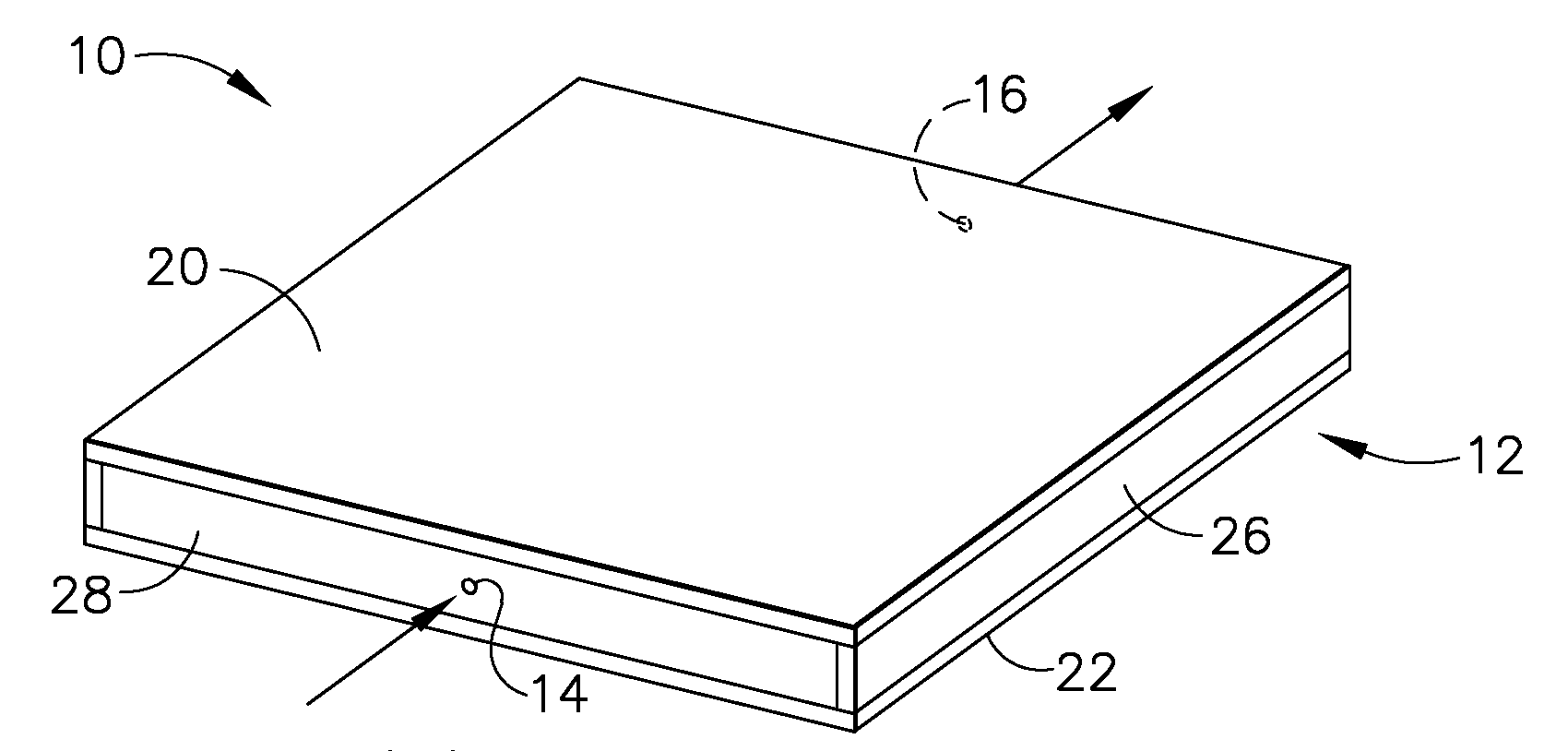
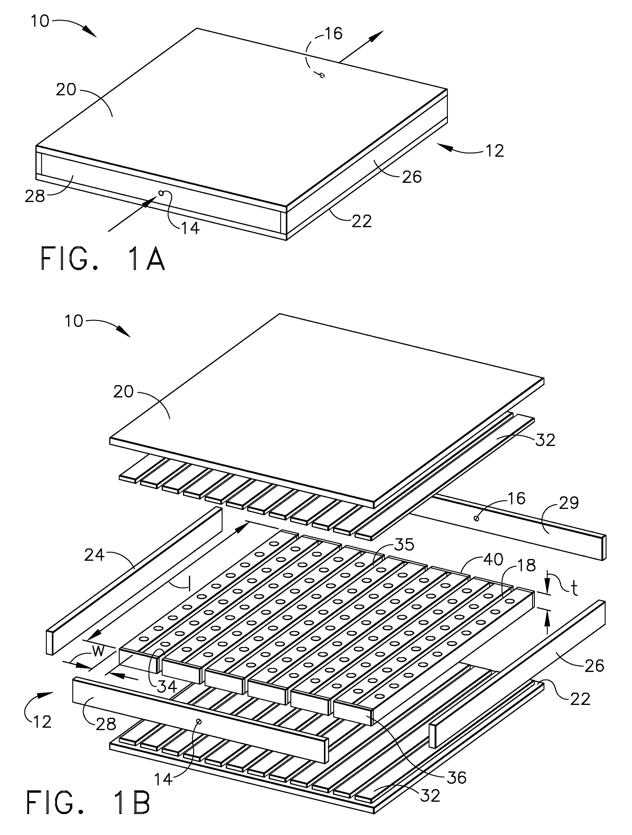
[0026]Referring to FIGS. 1A and 1B, an exemplary embodiment of a cold plate 10 is shown. The cold plate 10 includes a housing 12 and a plurality of ceramic foam strips 18 disposed within the housing 12. The housing 12 includes a top and bottom cover plates 20, 22 respectively, side plates 24 and 26, a front manifold plate 28 and a rear manifold plate 29. The front manifold plate 28 includes an inlet port 14, and the rear m...


PUM


Abstract

A cold plate and method for cooling using the cold plate are disclosed. The cold plate includes a housing having hyperporous, microchannel ceramic foam strips disposed therewithin. A plurality of plugs formed from a high thermal conductivity material are disposed into the ceramic foam strips. Heat is transferred in an extremely efficient manner by leveraging the high thermal conductivity of the plugs to transfer the energy deep into a high internal surface area ceramic foam, which in turn transfers the heat to a coolant via convection. Channels between the foam strips form coolant inlet and outlet plenums, which results in minimal coolant pressure drop through the cold plate. In one example, an exemplary cold plate may provide cooling to one or two printed circuit boards. In another example, a cold plate may be disposed within a heat exchanger housing to provide cooling to a fluid.

Description

CROSS REFERENCE TO RELATED APPLICATION[0001]This application is a continuation-in-part of U.S. Utility application Ser. No. 11 / 407,438, filed Apr. 20, 2006, entitled “CERAMIC FOAM COLD PLATE”, which is incorporated herein by reference in its entirety.FIELD OF THE INVENTION[0002]This invention relates generally to methods and apparatuses for cold plates that are used for convective cooling of high power electronics and avionics. The invention further relates generally to methods and apparatuses employing cold plate designs as heat exchanger cores for high efficiency compact heat exchangers and to methods and apparatuses employing cold plates for cooling of printed circuit boards.BACKGROUND OF THE INVENTION[0003]Integrated circuit chips, such as micro-processor chips, and other electronic components generate heat during operation. These components are generally mounted on printed circuit boards (PCBs). To help ensure proper operation, these components must generally be kept at an oper...

Claims


Application Information

Patent Timeline
IPC IPC(8): F28D15/00
CPCB64D2013/0614F28F3/12H05K7/20509F28F21/04H05K7/20254F28F13/003
Inventor BEHRENS, WILLIAM WEBSTERTUCKER, ANDREW RICHARD
Owner THE BOEING CO
Why Eureka
Try Eureka