Charge pump regulator and method of producing a regulated voltage

Active Publication Date: 2008-08-21
RICHTEK TECH
View PDF3 Cites 24 Cited by
  • Summary
  • Abstract
  • Description
  • Claims
  • Application Information

AI Technical Summary

Benefits of technology

[0018]Preferably, the charge pump regulator further comprises a wide bandwidth, high slew rate buffer for driving the current control element according to the output-dependent feedb

Problems solved by technology

Such circuit will cause large input ripple and thereby large supply voltage disturbance, and induce undesired low frequency noise subsequently.
It is not easy to process this low frequency noise, and very large and expansive filter is required to filter out the low frequency noise.
However, the current ripple in the discharge phase is still large.
Because of the smaller input current in the charge phase, this circuit will cause smaller supply voltage disturbance

Method used


Image

  • Charge pump regulator and method of producing a regulated voltage
  • Charge pump regulator and method of producing a regulated voltage
  • Charge pump regulator and method of producing a regulated voltage

Examples


Example

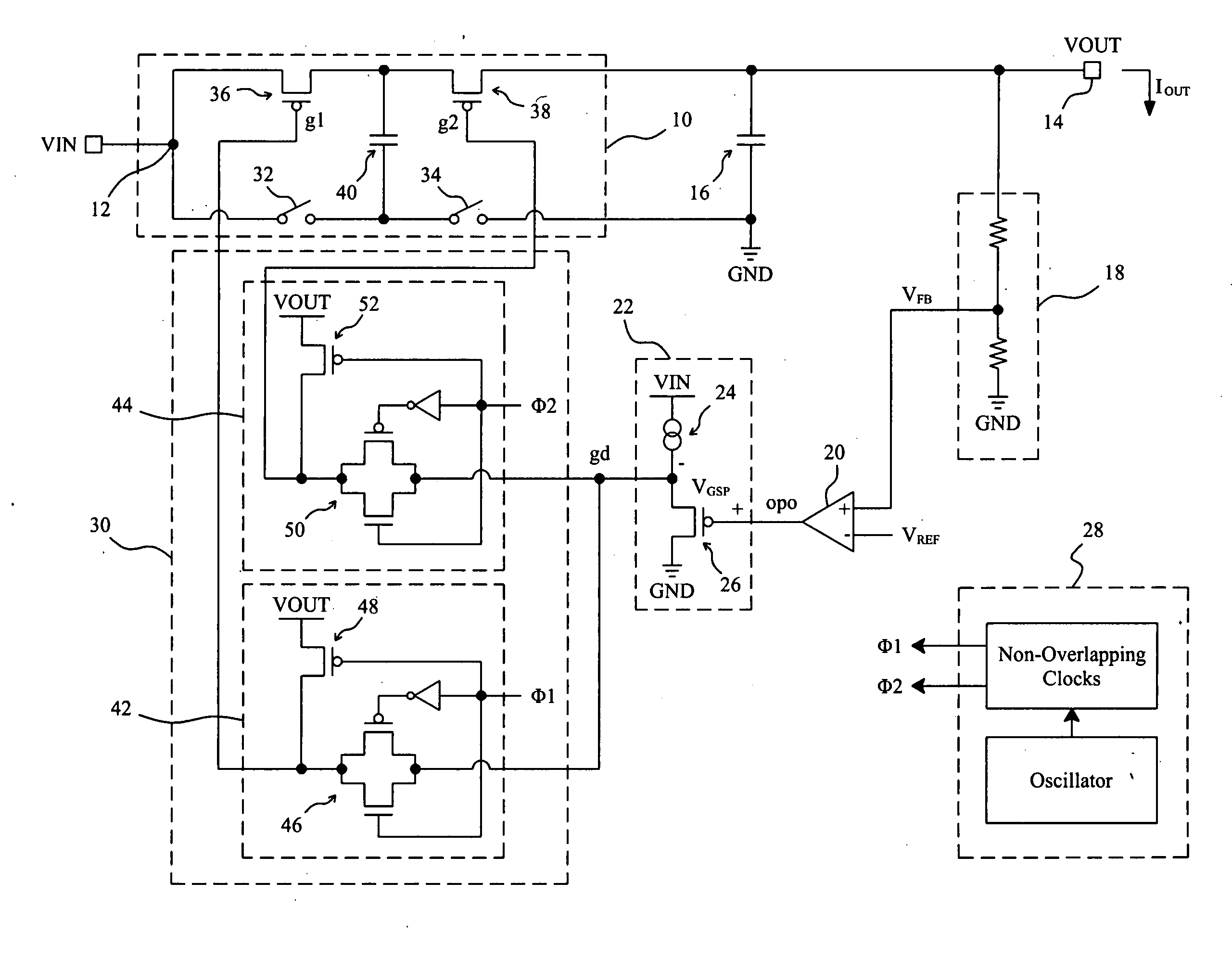
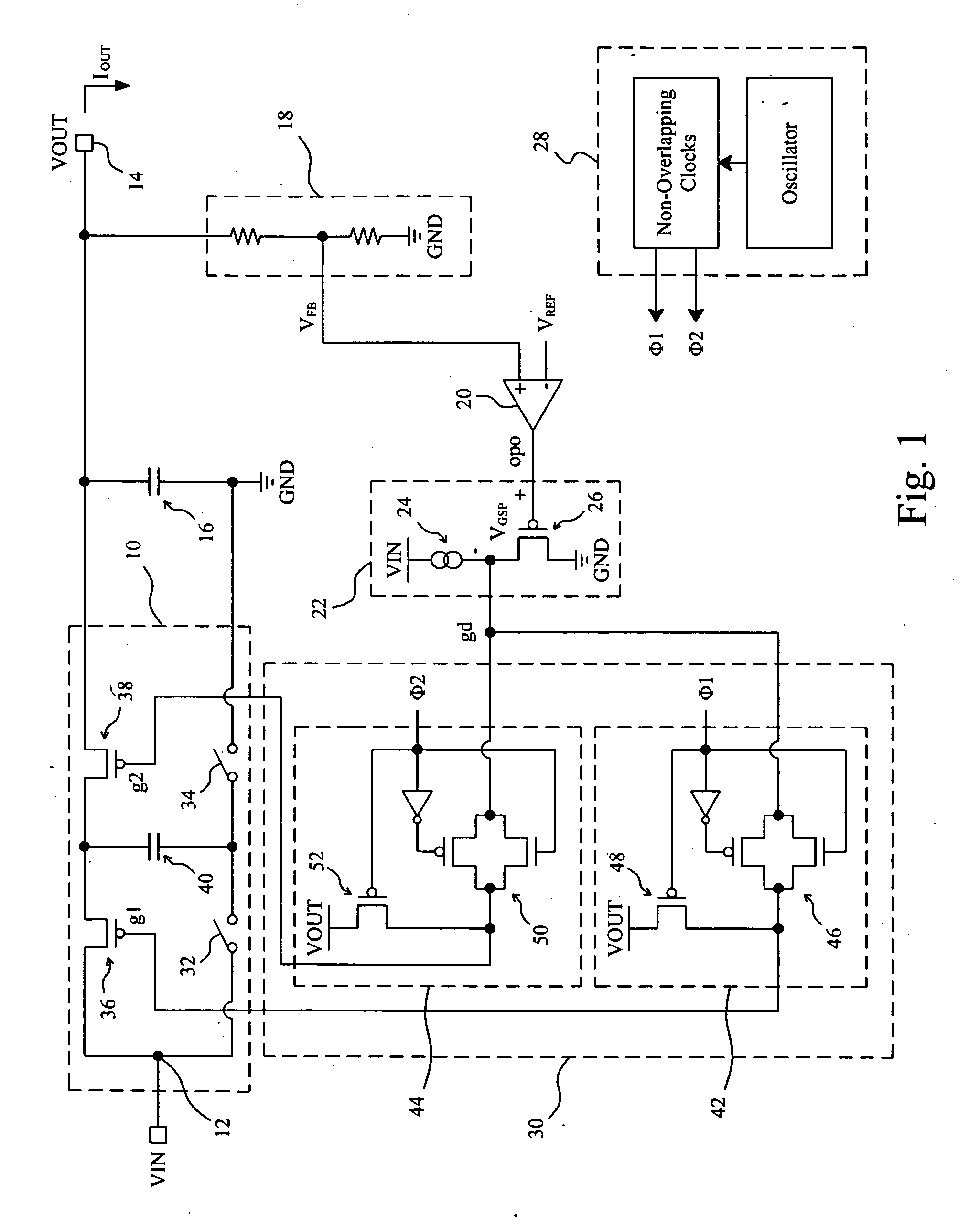
[0034]FIG. 1 shows a x1 / x2 boost-type charge pump regulator, which comprises a charge pump 10 connected between an input terminal 12 and an output terminal 14, an output capacitor 16 connected between the output terminal 14 and a ground terminal GND, and other control circuits to control the charge pump 10. A feedback loop comprises a resistor voltage divider 18 to produce a proportional voltage VFB from the output terminal 14 by dividing the output voltage VOUT thereon, and an amplifier 20 to amplify the difference between the proportional voltage VFB and a reference voltage VRFE to produce an output-dependent feedback signal opo. A buffer 22 is used to produce a drive signal gd according to the feedback signal opo. In this embodiment, the buffer 22 comprises a current source 24 and a PMOS transistor 26 connected in series between a power input VIN and a ground terminal GND, the gate of the PMOS transistor 26 is connected with the output-dependent feedback signal opo, and the drive...


PUM


Abstract

A charge pump regulator has a charge pump to establish a charge path and a discharge path alternately, so as to produce a regulated voltage on an output terminal. The charge pump has at least a current control element on the charge path or the discharge path to control the current flowing therethrough according to an output-dependent feedback signal.

Description

FIELD OF THE INVENTION[0001]The present invention is related generally to a charge pump regulator and, more particularly, to a high current charge pump regulator.BACKGROUND OF THE INVENTION[0002]As described in U.S. Pat. No. 6,411,531 to Nork et al., a pulse frequency modulation (PFM) charge pump regulator comprises a switch-capacitor network as a charge pump, in which switches are switched with a modulated switching frequency according to an output-dependent feedback signal, to connect a capacitor to a power supply or to an output terminal in order to charge and discharge the capacitor, so as to produce a regulated voltage on the output terminal. Such circuit will cause large input ripple and thereby large supply voltage disturbance, and induce undesired low frequency noise subsequently. It is not easy to process this low frequency noise, and very large and expansive filter is required to filter out the low frequency noise.[0003]U.S. Pat. No. 6,411,531 to Nork et al. also described...

Claims


Application Information

Patent Timeline
IPC IPC(8): H03L7/06
CPCH02M2001/0045H02M3/07H02M1/0045
Inventor LIN, SHUI-MUHUANG, TSUNG-WEICHEN, JIEN-SHENG
Owner RICHTEK TECH
Why Eureka
Try Eureka