
Excimer laser device operable at high repetition rate and having high band-narrowing efficiency

Active Publication Date: 2008-08-21
USHIO DENKI KK +1
View PDF3 Cites 21 Cited by
  • Summary
  • Abstract
  • Description
  • Claims
  • Application Information

AI Technical Summary

Benefits of technology

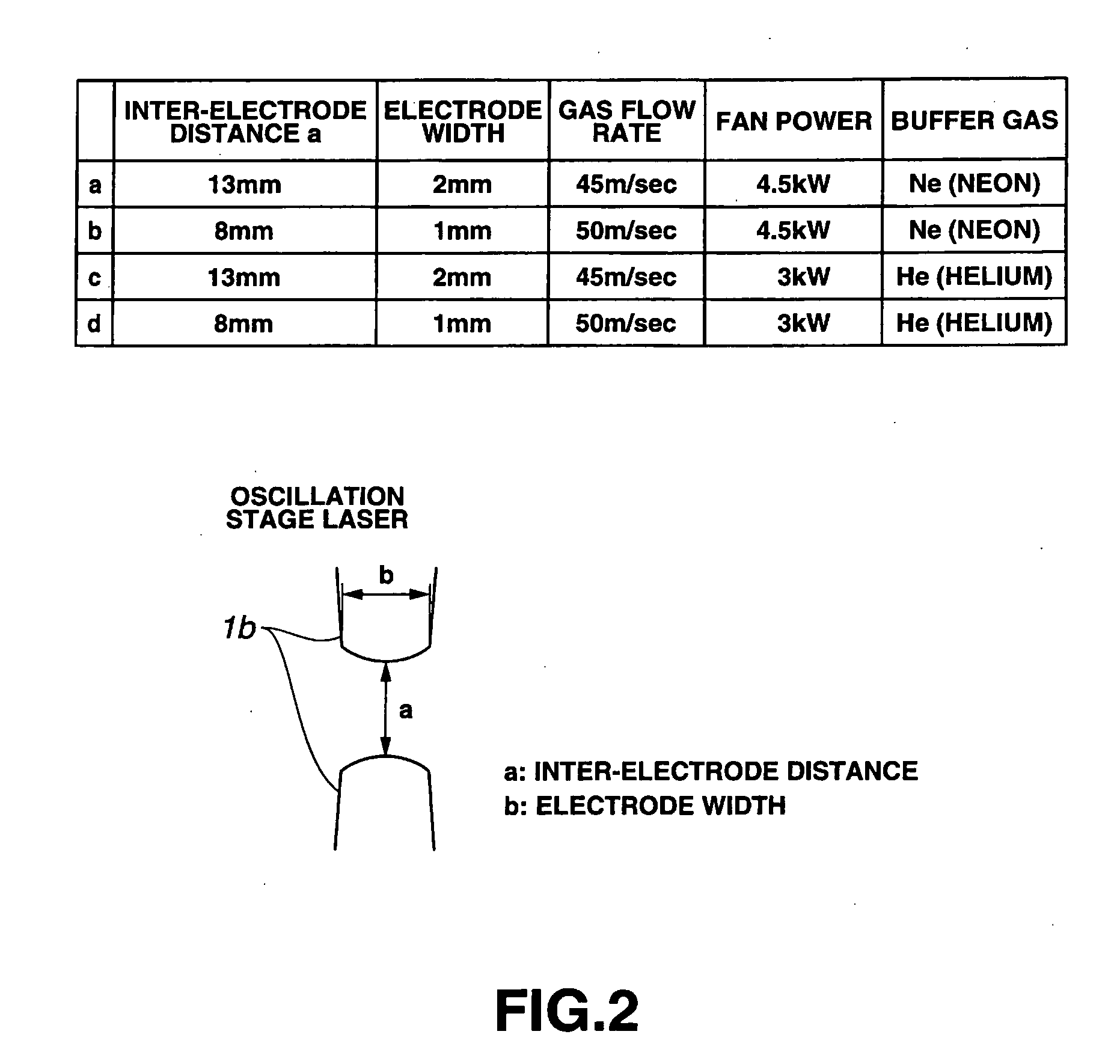
[0150](1) The discharge width can be set to a desired value as designed by setting the electrode width to 1 to 2 mm and setting the aspect ratio between the electrode width and the electrode interval to 0.25 to 0.125.
[0151]This enables stable oscillation at a high repetition rate without deteriorating the band-narrowing efficiency. The need is also eliminated to increase the power supplied to the motor for driving the fan for generating gas flow.
[0152](2) The discharge resistance can be optimized with respect to the discharge width by setting the aspect ratio between the electrode width and the electrode interval to 0.25 to 0.125. This makes it possible to generate electric discharge in a form as designed even if there is a certain degree of disturbances such as insufficient gas flow rate. This also significantly contributes to stabilization of the electric discharge during high repetition rate operation.
[0153](3) The discharge excited laser device according to the present invention can be used as an oscillation stage laser in a two-stage laser device having an oscillation stage laser (MO) and an amplifier (PA) or amplification stage laser (PO), so that the oscillation stage laser (MO) can be operated stably at a frequency of 10 kHz or higher without deteriorating the band-narrowing efficiency.

Problems solved by technology

A primary problem to be solved for putting high repetition rate lasers into practical use is a problem of power requirement.
The former of the two possible measures is much more difficult for putting the laser in practical use.
This power is comparable to the discharge input power used for laser oscillation, and is not allowable in view of the efficiency.
In addition, the increased input means that the amount of heat generated in the device is high, which may impair the stability of the device.

Method used


Image

  • Excimer laser device operable at high repetition rate and having high band-narrowing efficiency
  • Excimer laser device operable at high repetition rate and having high band-narrowing efficiency
  • Excimer laser device operable at high repetition rate and having high band-narrowing efficiency

Examples


Embodiment Construction

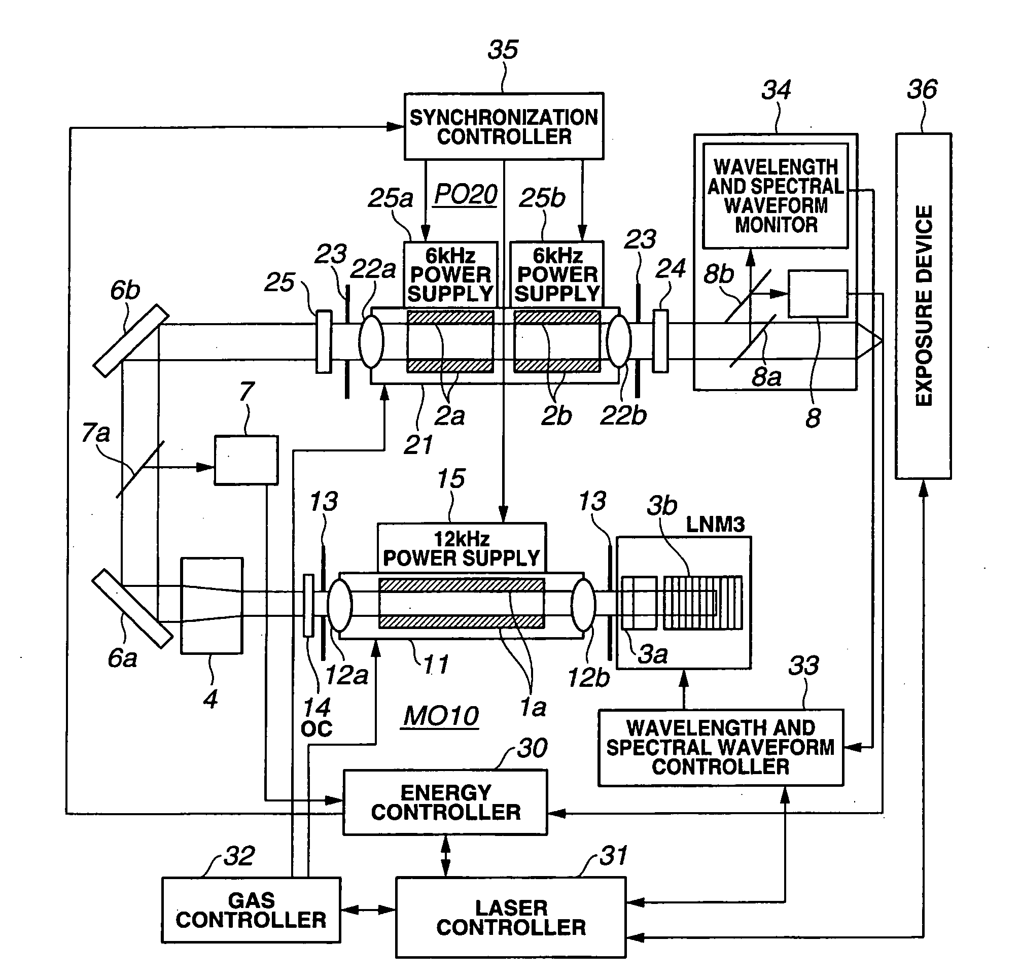
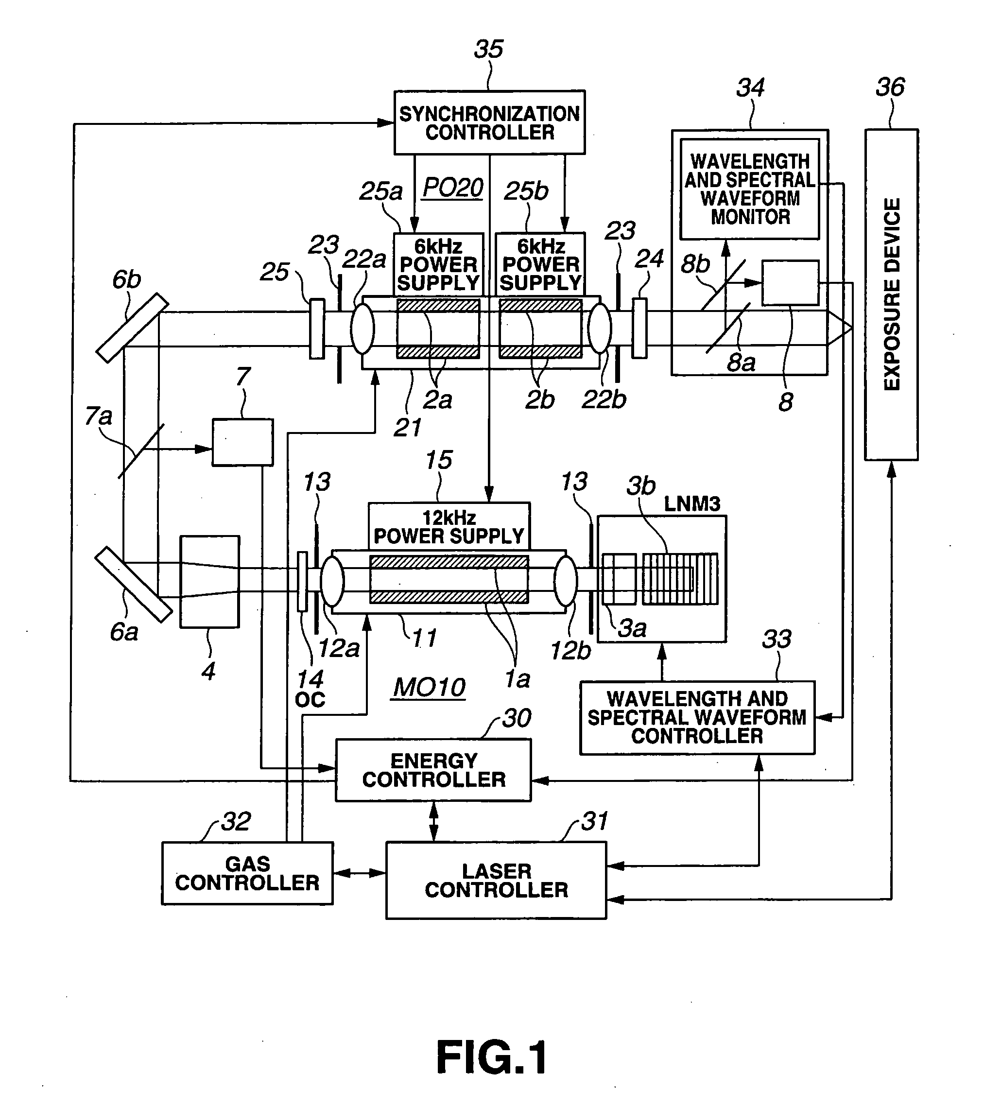
[0169]Embodiments of the present invention will be described. FIG. 1 shows a configuration example in which the present invention is applied to a MOPO-type laser device employing a double-chamber system.

[0170]As shown in FIG. 1, the MOPO-type laser device has an oscillation stage laser (MO) 10 for outputting laser light with a narrow spectral line width, and an amplification stage laser (PO) 20 for amplifying and oscillating the laser light from the oscillation stage laser (MO) 10 by means of an optical resonator. The laser light from the MO is injected into the amplification stage laser 20 via a beam expander 4 for expanding the beam in the direction of the discharge gap and two high reflection (HR) mirrors 6a and 6b.

[0171]The oscillation stage laser (MO) 10 has a band-narrowing module (hereafter, sometimes referred to as the “LNM”) 3 provided therein with a prism beam expander 3a and a grating (diffraction grating) 3b, and a laser resonator is formed by these optical elements in ...


PUM


Abstract

A narrow-band discharge excited laser device including a laser chamber having a laser gas sealed therein, a pair of electrodes provided within the laser chamber to face each other with a predetermined distance therebetween, a band-narrowing module having a magnifying prism and a grating and receiving laser light passing through a slit, and a cross-flow fan circulating the laser gas passing between the electrodes, in which a pulsed voltage is applied from a high-voltage power supply to the pair of electrodes to generate electric discharge between the electrodes, and the pair of electrodes have a width of 1 to 2 mm, a ratio between the electrode width and the inter-electrode distance (electrode with inter-electrode distance) being 0.25 to 0.125.

Description

BACKGROUND OF THE INVENTION[0001]1. Technical Field[0002]The present invention relates to a narrow-band discharge excited excimer laser device and, in particular, to a narrow-band discharge excited excimer laser device for use in exposure devices, which is capable of high output, realizing high band-narrowing efficiency, and oscillating at a high repetition rate.[0003]2. Related Art[0004]It is believed that, as the technology node is further scaled down, for example for the technology nodes of 45 nm to 32 nm, double exposure techniques such as double patterning and increased NA (1.3 to 1.5) using immersion technique will become principal techniques for exposure devices using an ArF excimer laser as a light source.[0005]The followings are requirements for light sources for ArF laser exposure devices.[0006]1. A high repetition rate (10 kHz or higher) and high average output (100 W or higher) are required to ensure high dose stability and to increase throughput.[0007]2. Increased NA re...

Claims


Application Information

Patent Timeline
IPC IPC(8): H01S3/03
CPCH01S3/0057H01S3/036H01S3/038H01S3/0385H01S3/073H01S3/2325H01S3/0805H01S3/225H01S3/2251H01S3/2316H01S3/08036
Inventor HORI, TSUKASAISHIHARA, TAKANOBUKAKIZAKI, KOUJI
Owner USHIO DENKI KK
Learn More