Method and system for improving uplink performance

a technology of uplink and communication method, applied in diversity/multi-antenna system, site diversity, polarisation/directional diversity, etc., can solve the problems of reducing the snr of the uplink signal, increasing the noise level, etc., and achieving negative financial impact, reducing the distance between the antennas, and restricting the dynamic range

Active Publication Date: 2008-08-21
CORNING OPTICAL COMM WIRELESS
View PDF38 Cites 61 Cited by
  • Summary
  • Abstract
  • Description
  • Claims
  • Application Information

AI Technical Summary

Benefits of technology

[0030]Another factor that impacts the uplink performance of a system is its Dynamic Range, the range of power levels, lowest to highest, that the system can handle. In a system composed of a well-designed DAS and a receiver, the receiver would typically have the more restricted dynamic range. The effect that a restricted dynamic range can have on a DAS deployment can be explained as follows. The strongest uplink signal is created when the terminal is as close as would be physically allowed to one of the DAS antennas (the Path Loss is the smallest possible). The weakest uplink signal is created when the terminal is as far away as is physically allowed from its nearest DAS antenna. The difference between the strongest signal and the weakest signal as described above must not exceed the dynamic range of the system. Since there is no way to limit the strongest signal, the only available way is to ensure the weakest signal is not too weak. As explained above, this can be accomplished by decreasing the distance between the antennas, with the associated negative financial impact.
[0031]A method that would allow a DAS to “smooth” out the differences between strong and weak uplink signals would help in overcoming the dynamic range limitations of the receiver and thus would allow for increasing the antenna spacing and the associated positive financial impact. Thus, improving the Uplink Performance of a DAS, and more particularly, its Dynamic Range behavior can provide tangible economical and functional benefits to a DAS.
[0032]In accordance with the invention, the SNR at an aggregation point can be improved by blocking or filtering the noise attributed to one or more of the branches that do not carry the signal. This can be accomplished by detecting whether there is signal activity from a particular terminal on any branch connected to an aggregation point and selectively blocking or filtering the input noise to be aggregated from one or more of the other branches connected to the aggregation point.
[0033]In accordance with the invention, the SNR of the uplink path can be improved by regenerating the signal at one or more points along the uplink path. This can be accomplished by using an Uplink Regeneration Block (URB) which can demodulate the signal and then re-modulate the signal at a very high SNR. While URBs can be located anywhere in the uplink signal path, there is a cost / performance tradeoff that can be used as a guide for determining the location and how may URBs are used. To reduce costs, the URBs can be located upstream of aggregation points in order to reduce the number of URB's used (lower cost) and improve the SNR of the aggregated signal, but to improve performance, the URBs should be located as far downstream as possible before the SNR has been deteriorated by the aggregation points (however many more URBs may be required).

Problems solved by technology

In another way, the level of the signal remains constant or is increased, but the noise level increases even more.
As a result, aggregating multiple uplink paths increases the noise level and therefore reduces the SNR of the uplink signal.
In some cases, the environment may exhibit a higher level of noise in the specific frequency range in which the signal of interest operates.
However, there is a cost penalty associated with doing this.
An amplifier however, introduces a minimal noise level which is typically higher than the Thermal noise level and increases commensurate with the gain of the amplifier, and thereby will always decrease the SNR of the signal.
The signal level does not change, while the noise level increases, and therefore the SNR is impaired.
As explained above, this can be accomplished by decreasing the distance between the antennas, with the associated negative financial impact.

Method used


Image

  • Method and system for improving uplink performance
  • Method and system for improving uplink performance
  • Method and system for improving uplink performance

Examples


Embodiment Construction

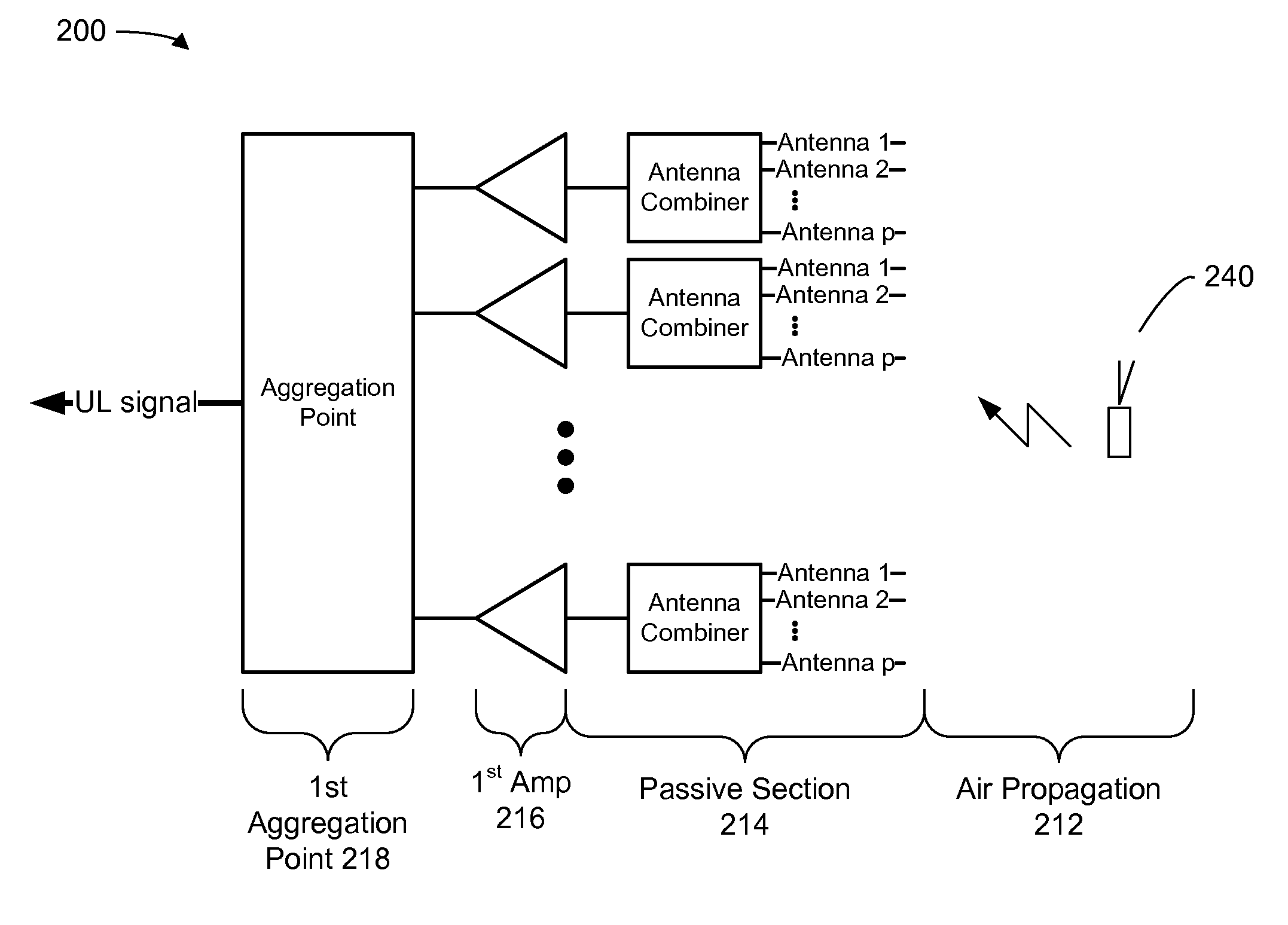
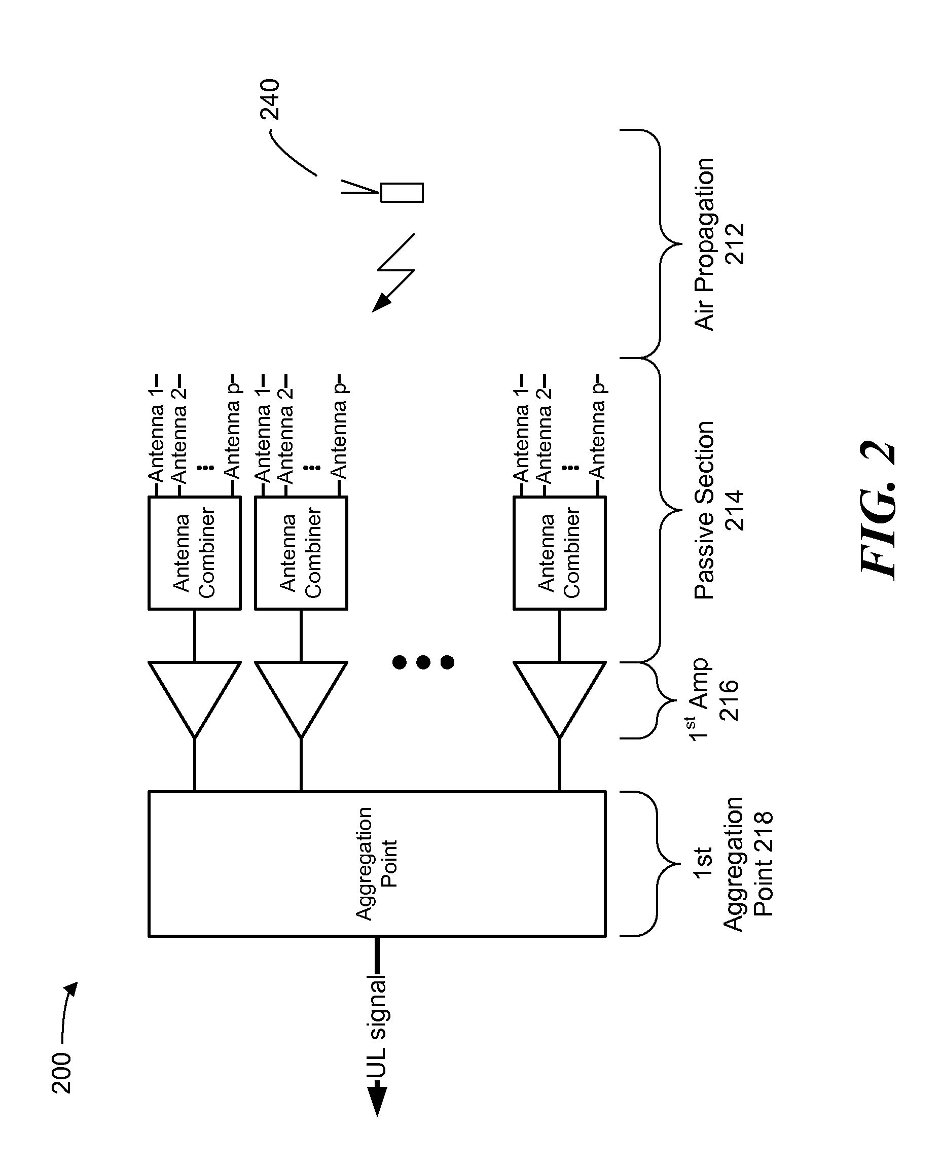
[0041]In accordance with the invention, two methods and systems for improving the Uplink Performance of a DAS are disclosed. Both methods allow for dynamic range “smoothing”, and thus further contribute to improving the uplink performance.

[0042]The Aggregation Point Noise Blocking (APNB) method and system minimizes noise accumulation in aggregation points of the DAS.

[0043]The Signal Regeneration method and system, includes regeneration of the signal along the uplink path of the DAS is order to improve the signal SNR to the values typical to a signal from a nearby transmitter.

Aggregation Point Noise Blocking

[0044]As explained above, at the aggregation points in the DAS, the noise from the various branches being aggregated is combined, thereby increasing the noise level, while the signal from a specific terminal, which typically would be present only on a single branch, does not increase accordingly. The result is a decrease in SNR which is proportional to the number of branches being...


PUM


Abstract

The present invention is directed to improvements for distributed antenna systems and more particularly to methods and systems for improving uplink communications. In one embodiment, Aggregation Point Noise Blocking provides for blocking or filtering the noise contributed by one or more of the branches coupled to an aggregation point that are not carrying the signal from a particular terminal. Signal activity from a given terminal on a particular branch can be identified and that information can be used to selectively block or filter the signal noise contributed by the other branches to an aggregation point. The selective blocking or filtering can also include an attenuation function to attenuate the signal and provide dynamic range smoothing. In another embodiment the signal can be regenerated to produce a signal that has a restored or very high SNR. An uplink regeneration block can be provided which demodulates the uplink signal to recover the transmitted information and then re-modulates the transmitted information to regenerate a signal at a restored or very high SNR.

Description

CROSS-REFERENCE TO RELATED APPLICATIONS[0001]This application claims any and all benefits as provided by law of U.S. Provisional Application No. 60 / 890,587 filed Feb. 19, 2007, which is hereby incorporated by reference in its entirety.[0002]This application is related to U.S. application Ser. No. ______, filed on Feb. 19, 2008 bearing Attorney Docket No. 29 / 823-529002US, which is hereby incorporated by reference in its entirety.STATEMENT REGARDING FEDERALLY SPONSORED RESEARCH[0003]Not ApplicableREFERENCE TO MICROFICHE APPENDIX[0004]Not ApplicableBACKGROUND[0005]1. Technical Field of the Invention[0006]The present invention is directed to improvements for distributed antenna systems and more particularly to methods and systems for improving uplink communications.[0007]2. Description of the Prior Art[0008]Distributed Antenna Systems (DAS) are used to provide and / or enhance coverage for wireless services such as Cellular Telephony and Medical Telemetry inside buildings and campuses. Th...

Claims


Application Information

Patent Timeline
Patent Type & Authority Applications(United States)
IPC IPC(8): H04B1/10
CPCH04B7/0874H04B7/0491H04L1/06H04B15/00H04B7/024H04B1/1027H04B1/109
Inventor OREN, YAIRSABAN, OFER
Owner CORNING OPTICAL COMM WIRELESS
Why Eureka
Try Eureka