

Metal Fluoride And Phosphate Nanocomposites As Electrode Materials
- Summary
- Abstract
- Description
- Claims
- Application Information
AI Technical Summary
Benefits of technology
Problems solved by technology
Method used
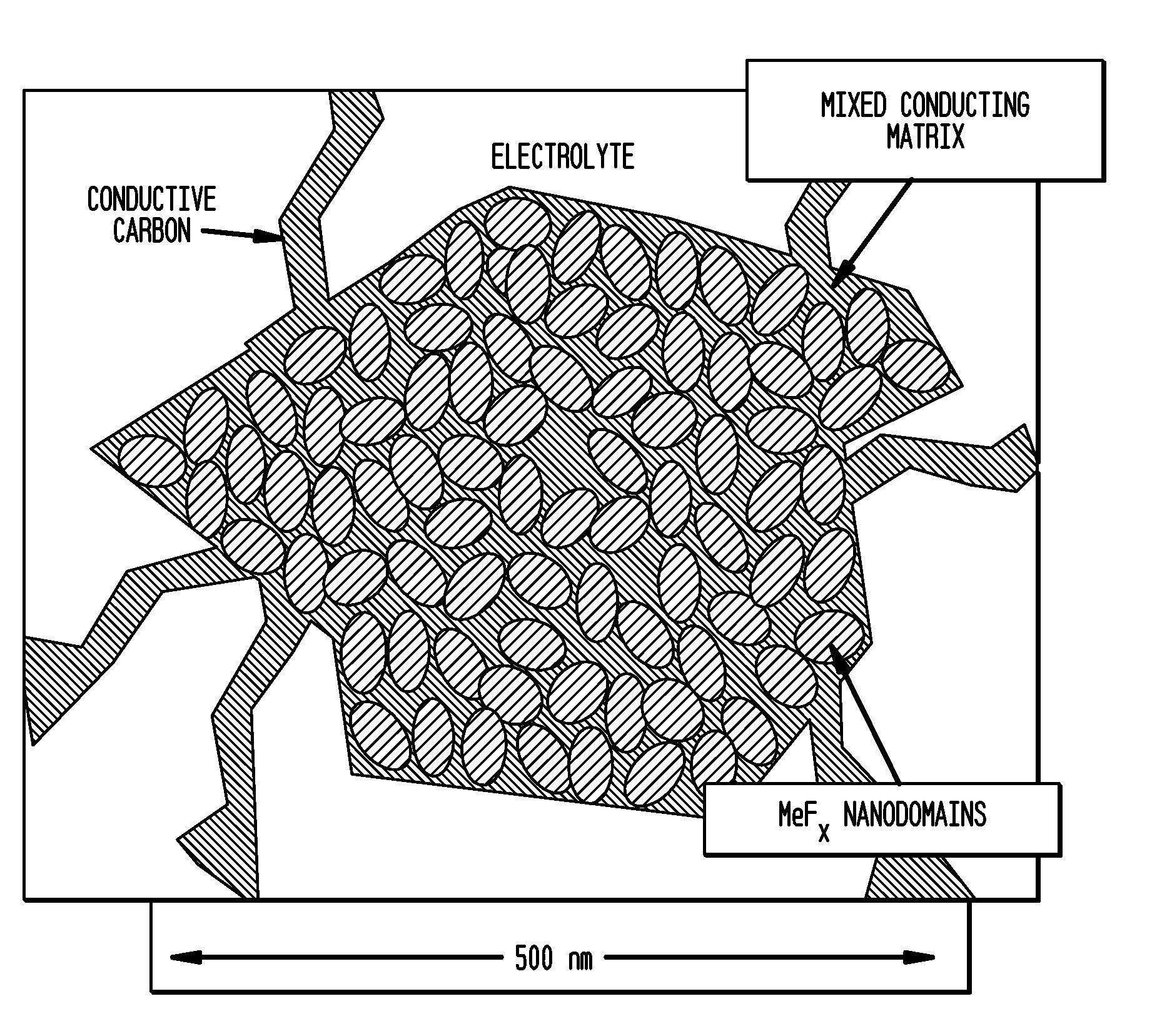
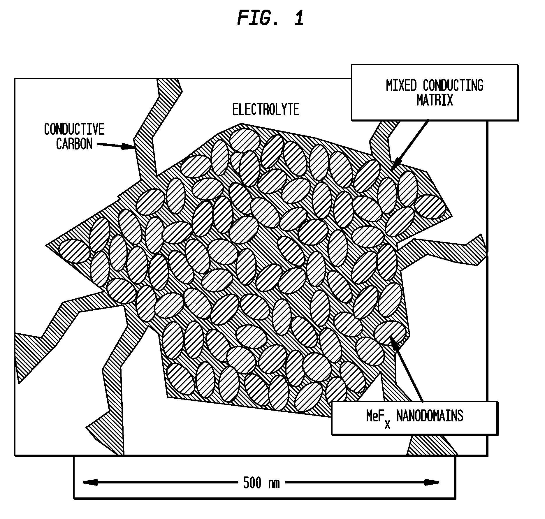
Image

Examples
example 1
Preparation of Copper Fluoride and Phosphate Nanocomposite with MoO3 Conductive Matrix with Lithium Metaphosphate
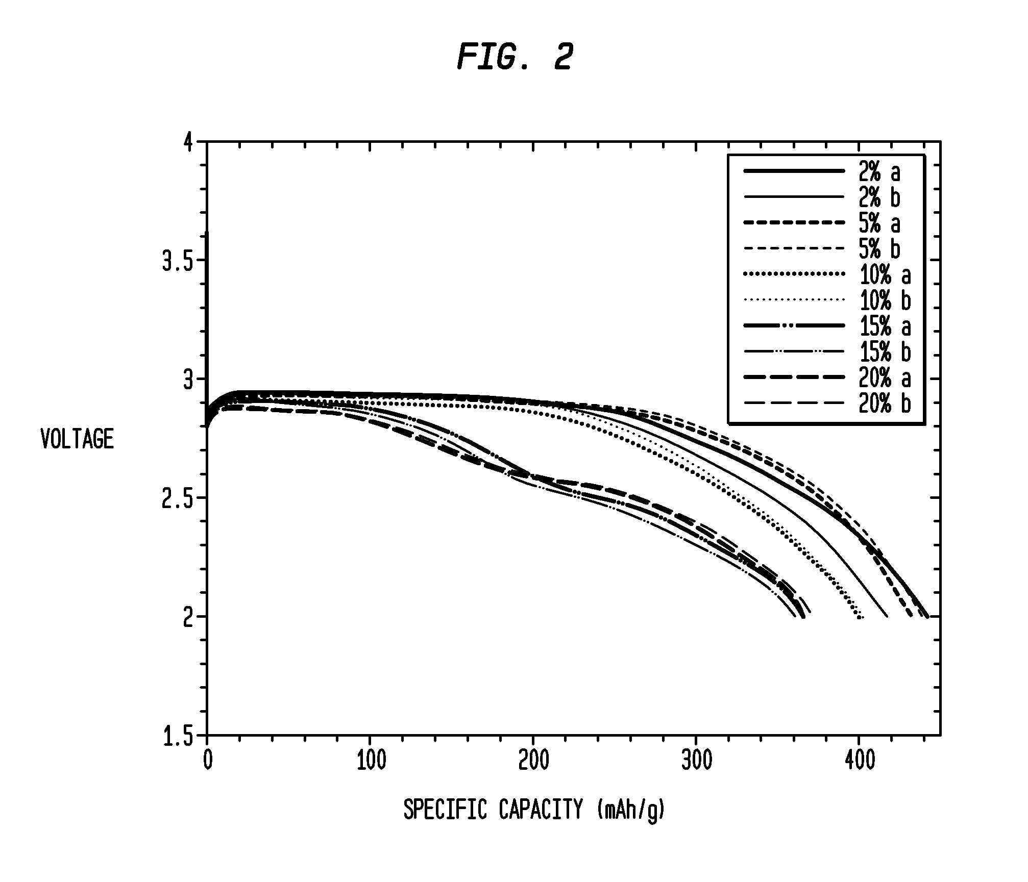
[0086]Approximately 1 g of CuF2, and 15% MoO3 were milled in a high-energy impact mill under a helium atmosphere for 20 min. and subsequently annealed at 200° C. before the sample was extracted. The resulting mixture is designated “CM” herein. CM was composed of crystallites of approximately 30 nm. After fabrication of CM, various weight percentages of lithium metaphosphate (Li3PO3—LiH2PO4) were mixed with the CM composition. Specifically, 2 weight % lithium metaphosphate; 5 weight % lithium metaphosphate, 10 weight % lithium metaphosphate; 15 weight % metaphosphate %; and 20 weight % lithium metaphosphate were mixed with the CM in different samples. A nanocomposite was formed by high energy milling of the composition for a period of 1 h, after which the composition was annealed at 250° C. for a period of 30 minutes in Argon. The compositions were fabricated into electrod...
example 2
Preparation of Copper Fluoride and Phosphate Nanocomposites with MoO3 Conductive Matrix with Lithium Metaphosphate Annealed at High Temperatures
[0092]CM compositions were fabricated as noted in Example 1. After fabrication, 10 weight % of lithium metaphosphate (Li3PO3—LiH2PO4) was mixed with the CM composition. A nanocomposite was formed by high energy milling the composition for a period of 1 h, after which the composition was annealed at various times and temperatures under a flowing Argon atmosphere. Specifically, the nanocomposite was annealed at 200° C., 250° C., and 300° C. The nanocomposites were annealed for 30 minutes and 2 hours at each temperature. The compositions were fabricated into electrodes and assembled into duplicate (a,b) electrochemical cells for evaluation in a manner which has been described previously. The cells were discharged at 7.58 mA / g at 24° C. and the resultant voltage profiles and capacity is shown in FIG. 4. As can be seen in FIG. 4, the specific cap...
example 3
Preparation of Copper Fluoride and Phosphate Nanocomposites with MoO3 Conductive Matrix with Lithium Dihydrogen Phosphate
[0094]CM compositions were fabricated as described in Example 1. After fabrication, various weight percentages of lithium dihydrogen phosphate (LiH2PO4) were mixed with the CM composition. Specifically, 10% lithium dihydrogen phosphate, 15% lithium dihydrogen phosphate, 20% lithium dihydrogen phosphate and 30% lithium dihydrogen phosphate were mixed with the CM. A nanocomposite was formed by high energy milling the composition for a period of 1 h after which, the composition was annealed at 250° C. for a period of 30 minutes in Argon. The compositions were fabricated into electrodes and assembled in duplicate (a, b) into electrochemical cells for evaluation as described above. The cells were discharged at 7.58 mA / g at 24° C. and the resultant voltage profiles and capacity is shown in FIG. 6. The specific capacity is exemplary for all the compositions with many com...
PUM
 Abstract
Description
Claims
Application Information