
Measuring device for measuring hitting parameters of a golf club and associated calibration device

Inactive Publication Date: 2008-08-21
HGM - HAAG GOLF MESSTECHN
View PDF17 Cites 31 Cited by
  • Summary
  • Abstract
  • Description
  • Claims
  • Application Information

AI Technical Summary

Benefits of technology

[0037]The object of the invention is to provide a measuring device for measuring the hitting parameters which is easy to handle, mobile, compact, applicable indoor and outdoor, with and without golf ball, usable for right- and left hander alike, and is nevertheless cost / effective, which uses a high-precision measuring method and to provide a calibration device that ensures trustworthy data.
[0047]5. horizontal angle of approach in / out Aio can be determined additionally.An additional facility with a further reflective light barrier according to an embodiment of the invention or the employment of a measuring system according to a further embodiment of the invention with a group of reflectors according to another aspect of the invention allows for the measurement of the
[0053]The apparatus according to the invention is particularly applicable in golf training centers. With the help of the attained data, golf teachers can provide much more specific training hints to improve the performance of their golf students. But also technically interested golf apprentices, who want to examine in depth the “why” of their unsuccessful swing, may acquire the apparatus according to the invention and tee off balls at the driving range or train the optimal swing at home, also without golf ball. The particular advantage is the high learning efficiency, because the attained data are presented instantaneously after accomplishment of the swing, at a time, when the apprentice still gets feedback about his physical approach from his musculature.

Problems solved by technology

In principle, this is a robust measurement method, but it is a disadvantage that the (infrared-) light source constitutes an annoyance in the view field of the player.
Further, the detectors in the playing surface are prone to contamination and / or to damaging by the club head.
A further disadvantage is the requirement of a special golf mat for the measurements.
However, this method does not solely use clearly defined times of beam interruption, but the natural ambient light and analog signals that represent the degree of shadowing effects on particular diffusor disks during the passage of the club head.
Thereby the analysis becomes difficult and is particularly problematic where the ambient light intensity varies quickly.
With this method very precise results may be achieved, but in practice it shows some severe disadvantages:1. A mirror has to be arranged and exactly aligned between the player and the tee.2. Another exactly aligned mirror must be attached to the club head which may be damaged in cases of imprecise ball contact.
The assembly is so bulky, that practice may just be possible in fixed cabins.
The hitting parameters are not determined in this way, the measurement setup is not qualified for that purpose.
A further disadvantage is the liability of the measurement to faults by the use of ball-shaped reflectors which necessitate the use of special filters.
The setup is not suited to determine the hitting parameters.
Since the radar transceiver is arranged behind the golf ball in the heading direction of the ball flight, there is always some risk that badly struck golf balls may hit and damage the radar unit after takeoff.
Hitting parameters cannot be assessed with such a simple measuring equipment.
However, putting with a golf ball is precluded during this kind of training, else the mirror would be damaged.
Although an embodiment is mentioned, in which the mirror is offset laterally to allow for putting a golf ball, such a setup is not suited for full swings, be it with or without ball.
The great number of infrared reflective light barriers makes the proposed system expensive.
Further, the current needed alone for the infrared emitters sums up to significantly more than 3 A, which impedes battery-based operation.
Such a setup is damageable by too lowly accomplished swings, particularly because the position and adjustment of all light barriers is essential for their aforementioned function.
A good temporal resolution of the proposed design can only be expected if the club head passes the mat at low distance.
Else the aperture angle of the sensors is likely to produce strong time-jitter of the output signals, which renders the measurement imprecise or useless.
The necessarily short working distance causes another problem.
This necessitates expensive special designs (standard sensor approx.
1000 ), which in addition are exposed to the risk of damage by the club head.
A disadvantageous feature of this setup is the position of the laser source near the feet of the player, which constitutes a dangerous stumbling block.
Further, the applied, vertically pointing laser fans are either severely restricted in their power density or they can lead to irritation or even damage to the eyes in the vicinity of the orifice of the laser source.
USB cameras are inexpensive, indeed, but they offer bad frame rates (consumer type USB-cameras today 80 fps at maximum) and cannot be synchronized to the stages of the swing.
Such an image analysis is extensive, expensive and coarsely rasterized.
Another disadvantage of this kind of analyzer is further, that to the golf ball reflective dots have to be attached, which might get damaged at each stroke.
Further, it is not possible to play without golf ball with such a measuring setup.

Method used


Image

  • Measuring device for measuring hitting parameters of a golf club and associated calibration device
  • Measuring device for measuring hitting parameters of a golf club and associated calibration device
  • Measuring device for measuring hitting parameters of a golf club and associated calibration device

Examples


Embodiment Construction

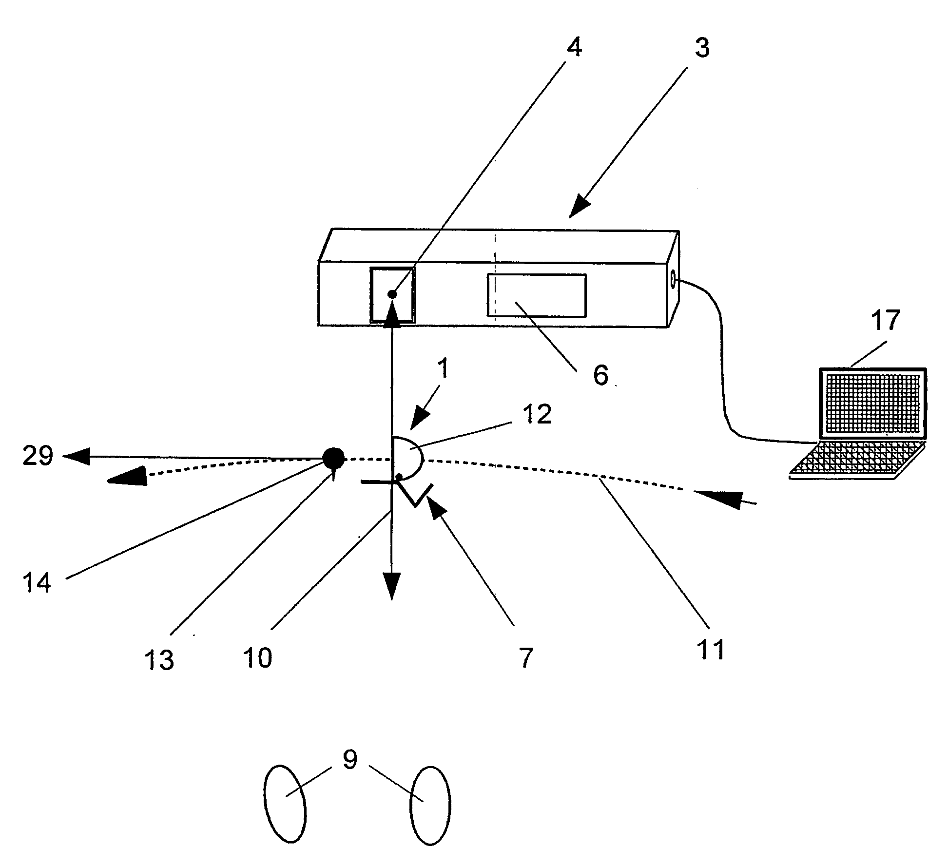
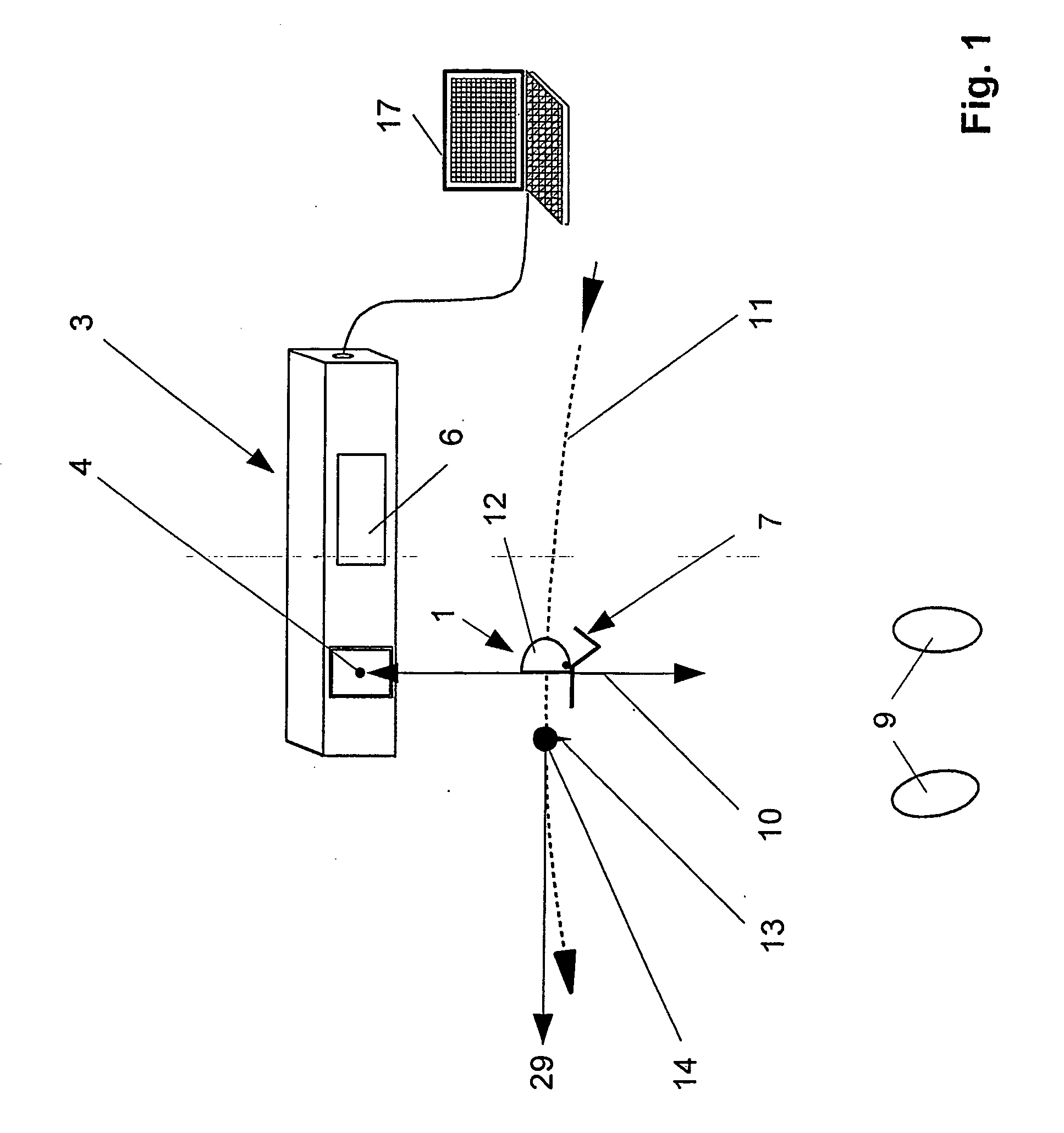
[0075]The measuring system pertaining to the invention for measuring hitting parameters of a gulf club 1 as shown in FIG. 1 consists of a measuring device 3 and a group of reflectors 7 attached to the golf club 1. The measuring device 3 is arranged opposite to the golfer 9 and comprises at least one horizontally pointing reflective light barrier 4 and a data acquisition unit 6, preferably integrated into the measuring device. The reflective light barrier 4 sends a beam 10 at right angle to the ideal swing path 11 of the club head 12 near the tee 13 and / or the golf ball 14, where the group of reflectors 7 that is attached to the golf club 1, upon passing the beam 10, generates measuring data as impulses that are sent back to the reflective light barrier, which then are captured by the data acquisition unit 6 and forwarded to an information output- and storage unit 17.

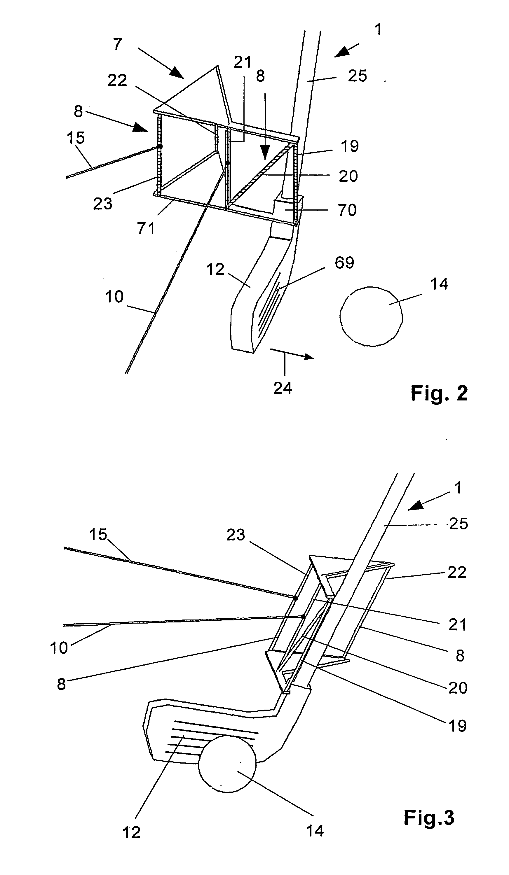
[0076]FIG. 1 shows a low / wide embodiment of a group of reflectors 7, that is specified in the following with the help ...


PUM


Abstract

A measurement setup to determine hitting parameters of a golf club includes a group of reflectors with at least two strip-shaped reflectors with retroreflective surfaces applied to the golf club shaft. The group of reflectors is attached to the club shaft with a detachable, yet tight clamp-connection. At least three retroreflective areas are arranged in a determined geometry at the club shaft and / or at the group of reflectors. At least one first reflective light barrier sends its beam at a right angle to the ideal swing path of the club head near the tee and / or the golf ball at the group of reflectors. During the penetration of the beam the three strip-shaped retroreflective surfaces elicit temporally staggered pulse-shaped signals that the receiver of the first reflective light barrier receives and which it transmits to the data acquisition device. A calibration setup is also provided.

Description

CROSS REFERENCE TO RELATED APPLICATIONS[0001]Applicants claim priority under 35 U.S.C. 119 of German Application No. 10 2005 046 085.2 filed Sep. 26, 2005. Applicants also claim priority under 35 U.S.C. 120 of International Application No. PCT / DE2006 / 001700. This application is a by-pass continuation-in-part application of said International Application No. PCT / DE2006 / 001700 filed Sep. 26, 2006. The International Application under PCT Article 21(2) was not published in English. The disclosure of the aforesaid International Application and German application are incorporated by reference.BACKGROUND OF THE INVENTION[0002]1. Field of the Invention[0003]The invention relates to a measuring device for measuring the hitting parameters of a golf club, including a measuring device with at least one horizontally pointing reflective light barrier, a data acquisition device integrated into the measuring device, reflectors with retro-reflective surfaces attached to the golf club in correspondin...

Claims


Application Information

Patent Timeline
IPC IPC(8): A63B69/36
CPCA63B69/3614A63B69/3632G01P3/68G01S7/4972G01S13/58G01S17/026G01S7/497G01S17/04
Inventor HAAG, HANS-JOACHIM A.GODDE, JOSEF
Owner HGM - HAAG GOLF MESSTECHN
Learn More