System and method for oxygen separation in an integrated gasification combined cycle system

a gasification combined cycle and oxygen separation technology, applied in the direction of combustible gas production, machines/engines, sustainable manufacturing/processing, etc., can solve the problems of reducing the net plant output and efficiency, and the cryogenic air separation process consumes significant amounts of electric power

Inactive Publication Date: 2008-08-28
SIEMENS ENERGY INC
View PDF23 Cites 100 Cited by
  • Summary
  • Abstract
  • Description
  • Claims
  • Application Information

AI Technical Summary

Problems solved by technology

The cryogenic air separation process consumes significant quant...

Method used


Image

  • System and method for oxygen separation in an integrated gasification combined cycle system
  • System and method for oxygen separation in an integrated gasification combined cycle system
  • System and method for oxygen separation in an integrated gasification combined cycle system

Examples


Embodiment Construction

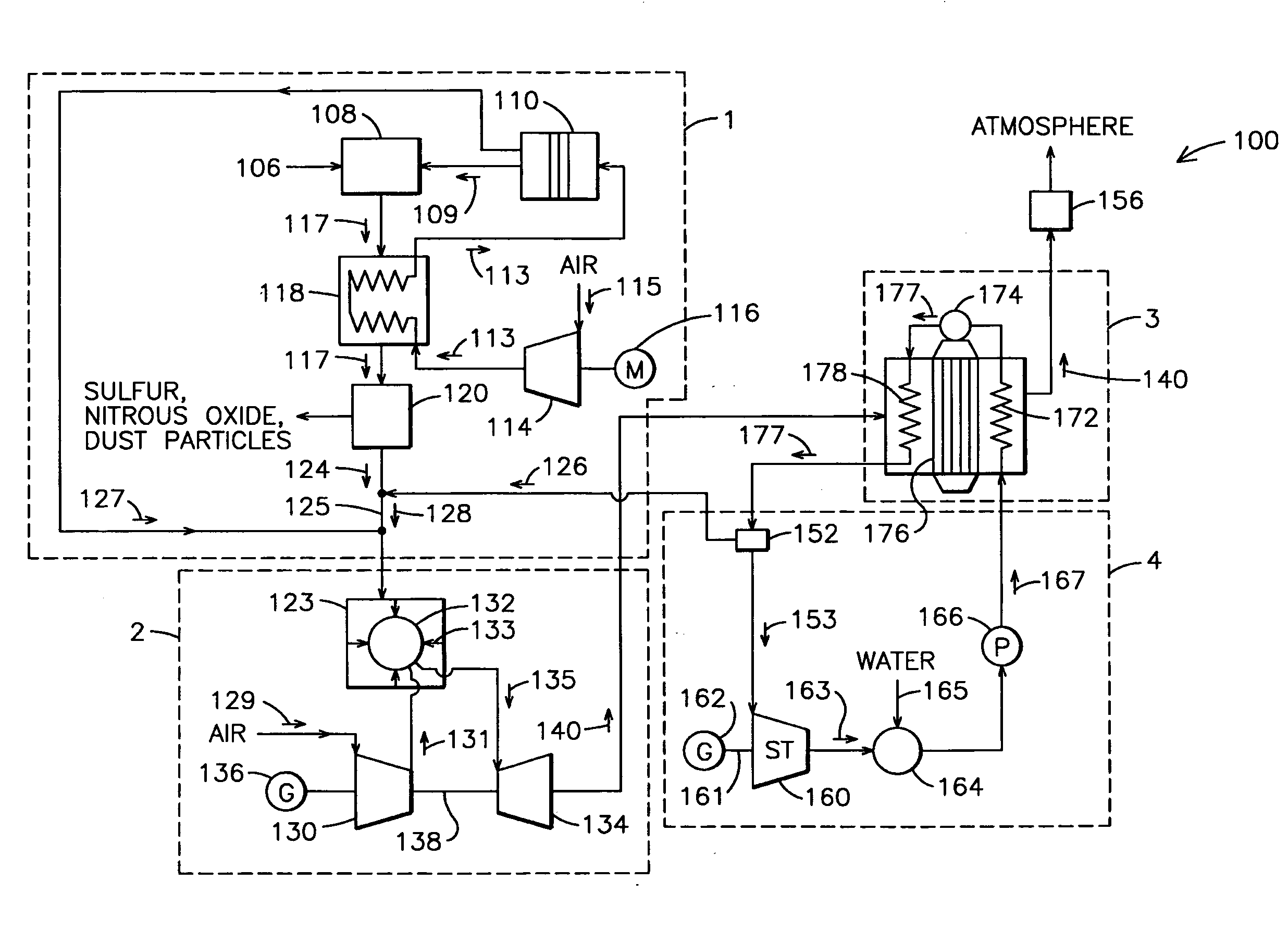
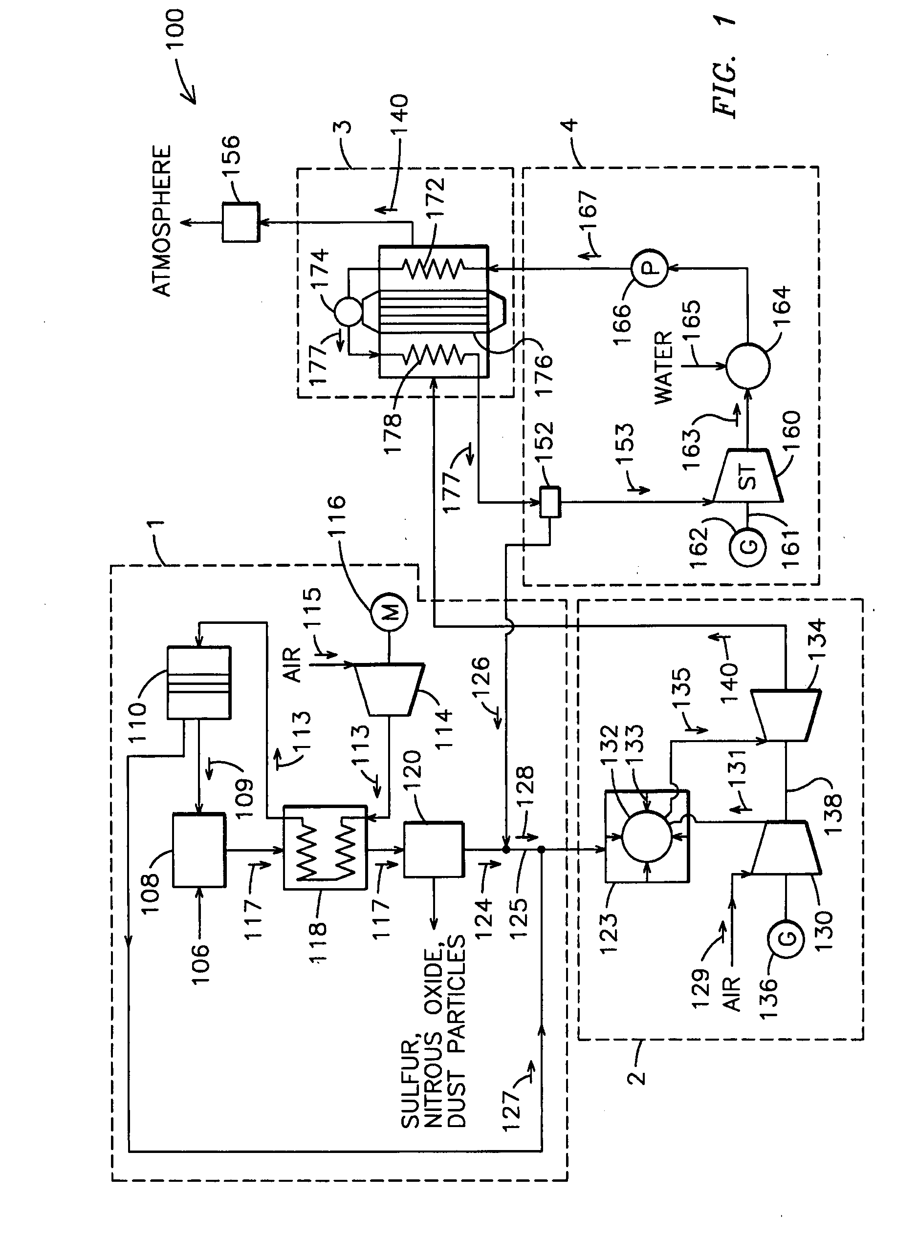
[0007]The invention comprises an IGCC system that integrates an air separation unit with recovery of sensible heat. In one embodiment a power generation system 100, shown in FIG. 1 comprises a gasification system 1, a gas turbine system 2, a Heat Recovery Steam Generator (HRSG) 3, and a steam turbine system 4, each of which may be configured in a conventional manner. The gasification system 1 includes a hydrocarbon fuel source 106, such as a coal slurry, a gasifier 108, an ITM air separation unit 110, an air compressor 114, a syngas cooler 118 and a gas cleaning stage 120. The gas turbine system 2 includes an air-compressor 130, a combustor 132, a gas turbine 134, and an electrical generator 136. The HRSG 3 comprises an economizer 172, a steam drum 174, an evaporator 176 and a super heater 178. The steam turbine system 4 includes a steam chest 152, a steam turbine 160, an electrical generator 162, a condenser 164 and a feed-water pump 166.

[0008]Oxygen 109 is provided to the gasifier...


PUM


Abstract

An integrated gasification combined cycle power generation system (100). In one embodiment, shown in FIG. 1, a gasifier (108) is configured to generate synthetic gas (117) from a carbonaceous material (106) and an oxygen supply (109) with a cleaning stage (120) positioned to receive synthetic gas (117) from the gasifier (108) and remove impurities therefrom. A gas turbine combustion system (2) including a turbine (123) is configured to receive fuel (128) from the gasifier (108) and a first air supply (131) from a first air compressor (130). A steam turbine system (4) is configured to generate power with heat recovered from exhaust (140) generated by the gas turbine system (2) and an ion transport membrane air separation unit (110) includes a second air compressor (114) for generating a second air supply (113). A first heat exchanger (118) is configured to cool the synthetic gas (117) prior to removal of impurities in the cleaning stage (120) by flowing the second air supply (113) through the first heat exchanger (118) so that the second air supply (113) receives heat from the synthetic gas (117).

Description

FIELD OF THE INVENTION[0001]The present invention relates generally to power generation systems, and more particularly, to integrated gasification combined cycle systems.BACKGROUND OF THE INVENTION[0002]Integrated Gasification Combined Cycle (“IGCC”) systems are an economically attractive alternative to conventional fossil fuel power plants. They present an opportunity to deploy coal, an abundant resource, in an economical and clean manner, bringing improved efficiency over conventional coal-burning steam turbine power generation.[0003]In an IGCC system, a carbonaceous fuel such as coal is converted to a synthetic gas fuel, termed syngas, a mixture formed by partial oxidation at elevated temperatures. Syngas comprises carbon monoxide, hydrogen, and other gaseous constituents. Oxygen-blown gasifiers typically source oxygen from cryogenic Air Separation Units (ASUs) or from Ion Transport Membrane (ITM) Air Separation Units. Cryogenic ASUs employ a combination of compressors, heat exch...

Claims


Application Information

Patent Timeline
IPC IPC(8): F02C6/14
CPCC10J3/00Y02E20/16C10J2300/0916C10J2300/093C10J2300/0959C10J2300/165C10J2300/1671C10J2300/1675C10J2300/1678C10J2300/1861C10J2300/1869C10J2300/1876C10J2300/1884C10J2300/1892Y02E20/18C10K1/002C10K1/004C10K1/02C10J3/80Y02P20/10Y02P20/129
Inventor SULLIVAN, TERRENCE B.HUBER, DAVID J.
Owner SIEMENS ENERGY INC
Why Eureka
Try Eureka