Cooling System for Chamber of Ingot Growth Arrangement

a technology of ingot growth and cooling system, which is applied in the direction of crystal growth process, polycrystalline material growth, pressurized chemical process, etc., can solve the problems of defective products, cooling water leakage, and stagnation caused by vortices, and achieve the effect of increasing the cooling

Inactive Publication Date: 2008-08-28
QUALIFLOWNARATECH
View PDF1 Cites 3 Cited by
  • Summary
  • Abstract
  • Description
  • Claims
  • Application Information

AI Technical Summary

Benefits of technology

[0020]In the present invention, guide blades are provided in a base plate and a lid, which define a chamber, at positions at which cooling water creates stationary vortices, thus solving a problem of cooling water stagnation, thereby increasing a cooling effect.

Problems solved by technology

However, in the conventional base plate having the cooling system, because the guide line has an unevenly curved shape due to the electrode rod assembly holes and the vacuum pump connection holes, there is a problem in that stagnation due to vortices occurs near unevenly curved parts of the guide line.
Such stagnation causes a partial temperature drop in the chamber, thus resulting in a relatively sudden temperature rise, so that problems, such as defective products, may occur during a production process.
Furthermore, with the passage of time, due to metal corrosion, cooling water leakage may occur.
As well, because the ports interfere with the flow of the cooling water while the cooling water is discharged through the discharge hole, stagnation due to vortices occurs near curved parts of the ports.
Of course, such stagnation causes a partial temperature drop in the chamber, thus resulting in a relatively sudden temperature rise, so that problems, such as defective products, may occur during a production process.
Furthermore, with the passage of time, due to metal corrosion, cooling water leakage may occur.

Method used


Image

  • Cooling System for Chamber of Ingot Growth Arrangement
  • Cooling System for Chamber of Ingot Growth Arrangement
  • Cooling System for Chamber of Ingot Growth Arrangement

Examples


Embodiment Construction

[0048]Hereinafter, the present invention will be described in detail with reference to the attached drawings. Reference should now be made to the drawings, in which the same reference numerals are used throughout the different drawings to designate the same or similar components.

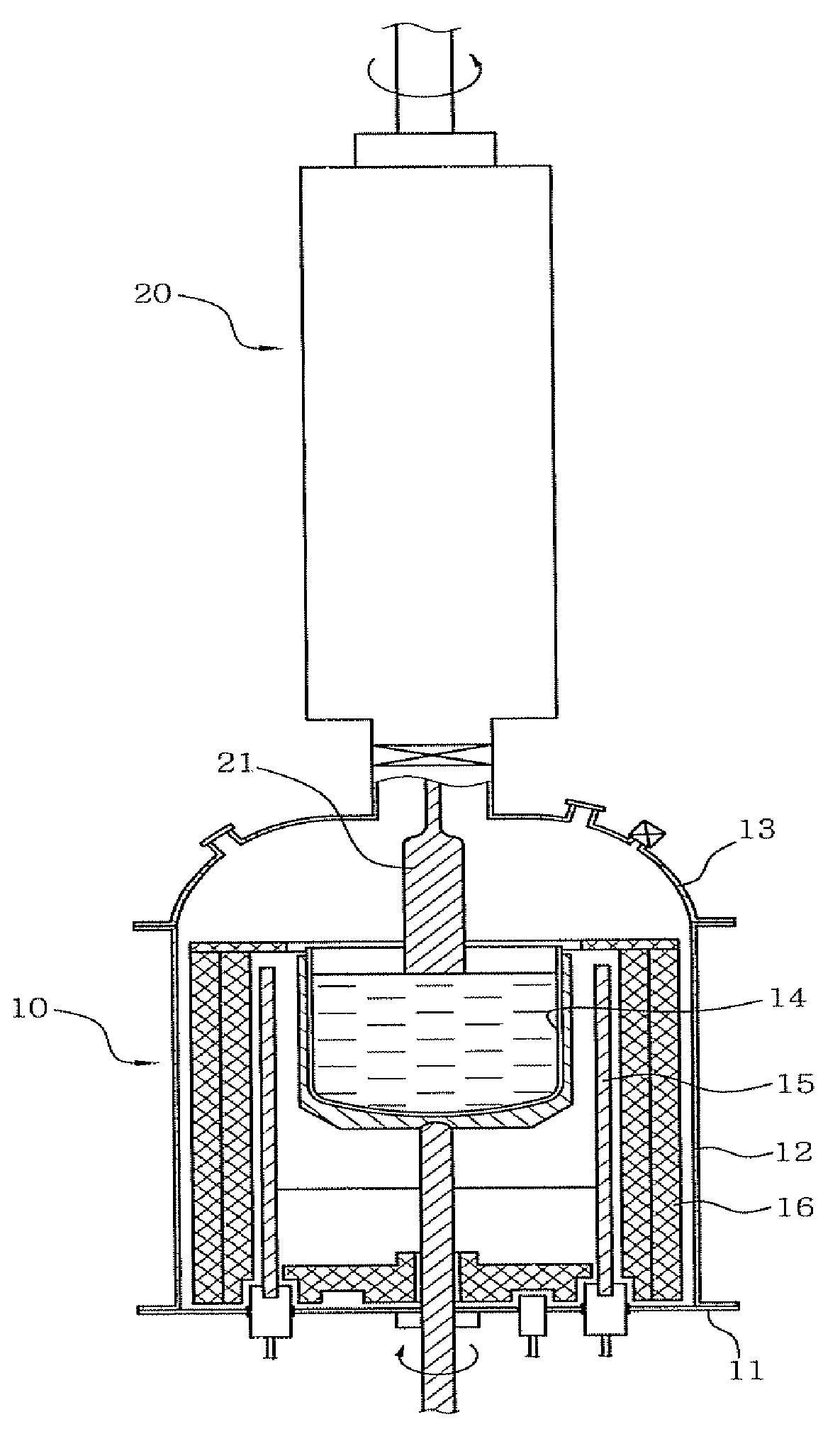
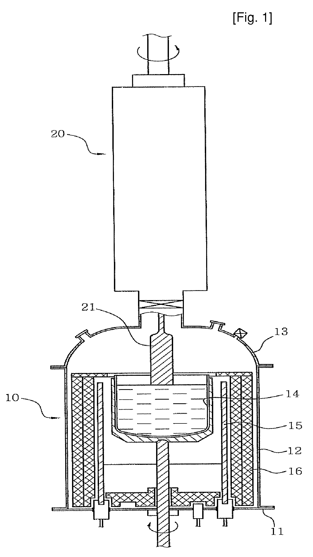
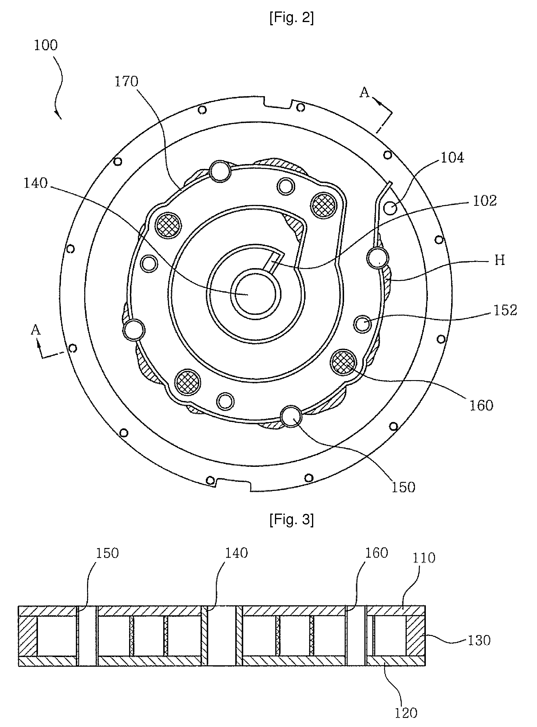
[0049]First, the construction of a chamber unit of an ingot growth apparatus will be explained herein below briefly for appreciation of the present invention. Typically, a chamber unit of the ingot growth apparatus includes a base plate, a main body, and a lid. Each of the base plate, the main body, and the lid has a cooling system therein to prevent it from being heated by a heater.

[0050]Furthermore, a quartz crucible, which melts polysilicon, is rotatably installed in the chamber unit. The heater is provided outside the quartz crucible to heat it. A thermal shield wall is provided outside the heater to prevent heat from being emitted to the outside of the chamber unit.

[0051]In the chamber unit having the a...


PUM

PropertyMeasurementUnit
sizeaaaaaaaaaa
diameteraaaaaaaaaa
distanceaaaaaaaaaa

Abstract

Disclosed herein is a cooling system for a chamber of an ingot growth apparatus. In the present invention, guide blades (180) are provided in a base plate (100) at positions adjacent to unevenly curved parts of a guide line (170), which is the base plate (100), and along which cooling water flows. Furthermore, guide blades (360) are provided in a lid (300) at positions adjacent to ports, which are provided in the lid (300) and interfere with the flow of cooling water. As such, in the present invention, the guide blades are provided in the base plate (100) and the lid (300), which define the chamber, at positions at which cooling water creates stationary vortices, thus solving a problem of water stagnation, thereby increasing a cooling effect.

Description

TECHNICAL FIELD[0001]The present invention relates, in general, to ingot growth apparatuses and, more particularly, to a cooling system for a chamber of an ingot growth apparatus in which guide blades are provided in a base plate and a lid, which define the chamber, thus providing a superior cooling effect.BACKGROUND ART[0002]Generally, as shown in FIG. 1, a silicon ingot growth apparatus includes a chamber unit 10, in which polysilicon is melted, and a growth tower unit 20, in which the molten polysilicon is brought into contact with a seed crystal, which slowly rises and thus grows as a silicon ingot having a predetermined diameter.[0003]Furthermore, a quartz crucible 12, which melts polysilicon, is rotatably installed in the chamber unit 10. A heater 14 is provided outside the quartz crucible to heat it. A thermal shield wall 16 is provided outside the heater to prevent heat from being emitted to the outside of the chamber unit.[0004]Typically, the chamber unit 10, having the abo...

Claims


Application Information

Patent Timeline
Patent Type & Authority Applications(United States)
IPC IPC(8): B22D11/124
CPCC30B15/14C30B35/002Y10T117/10Y10T117/1096Y10T117/1008Y10T117/1088Y10T117/1092C30B15/00
Inventor LEE, JONG GU
Owner QUALIFLOWNARATECH
Why Eureka
Try Eureka