Light-Emitting Device

a technology of light-emitting devices and phosphors, which is applied in the direction of discharge tubes/lamp details, discharge tubes luminescnet screens, gas-filled discharge tubes, etc., can solve the problems of the phosphor is difficult in itself to coat evenly with sb oxide films, and the wavelength conversion efficiency greatly degrades. , to achieve the effect of excellent display performance and aging or image display prevention

Inactive Publication Date: 2008-08-28
PANASONIC CORP
View PDF4 Cites 14 Cited by
  • Summary
  • Abstract
  • Description
  • Claims
  • Application Information

AI Technical Summary

Benefits of technology

[0015]As a particular embodiment where the light-emitting device of the present invention is the plasma display, the plasma display has a construction comprising: a front panel, a back panel that is arranged to face the front panel, barrier ribs that define the clearance between the front panel and the back panel, a pair of electrodes that are disposed on the back panel or the front panel, a discharged gas that is present at least between the electrodes and contains xenon that emits vacuum ultraviolet ray by applying voltage between the elect...

Problems solved by technology

In the meanwhile, when the aluminate phosphor is used, a wavelength conversion efficiency greatly degrades over time under some conditions of use.
However, although by the methods described in JP-A-S61-254689 and JP-A-2000-378 a certain effect of inhibiting thermal degradation during a production process is obtained, the methods can not sufficiently prevent degradation of properties caused by vacuum ultraviolet ray irradiation for aging or image display.
Further, even though the method described in JP-A-10-330746 is employed, it is difficult in itself to coat the phosphor evenly...

Method used


Image

  • Light-Emitting Device
  • Light-Emitting Device
  • Light-Emitting Device

Examples


Embodiment Construction

[0020]The light-emitting device of the present invention is provided with a phosphor layer containing a blue phosphor, and this phosphor layer includes an aluminate phosphor that contains Ba, Sr, Eu, Mg, Al and O as constituting elements at an atom-number ratio Ba:Sr:Eu:Mg:Al:O=p:q:r:1:w:17 wherein 0.70≦p≦0.95, 0≦q≦0.15, 0.05≦r≦0.20, p+q+r≧1, and 9.8≦w≦10.5 are satisfied.

[0021]It should be noted that the above constituting elements may be contained Just in a crystal of the aluminate phosphor, and the elements may be incorporated in the crystal lattice or intrude in the space between the lattice.

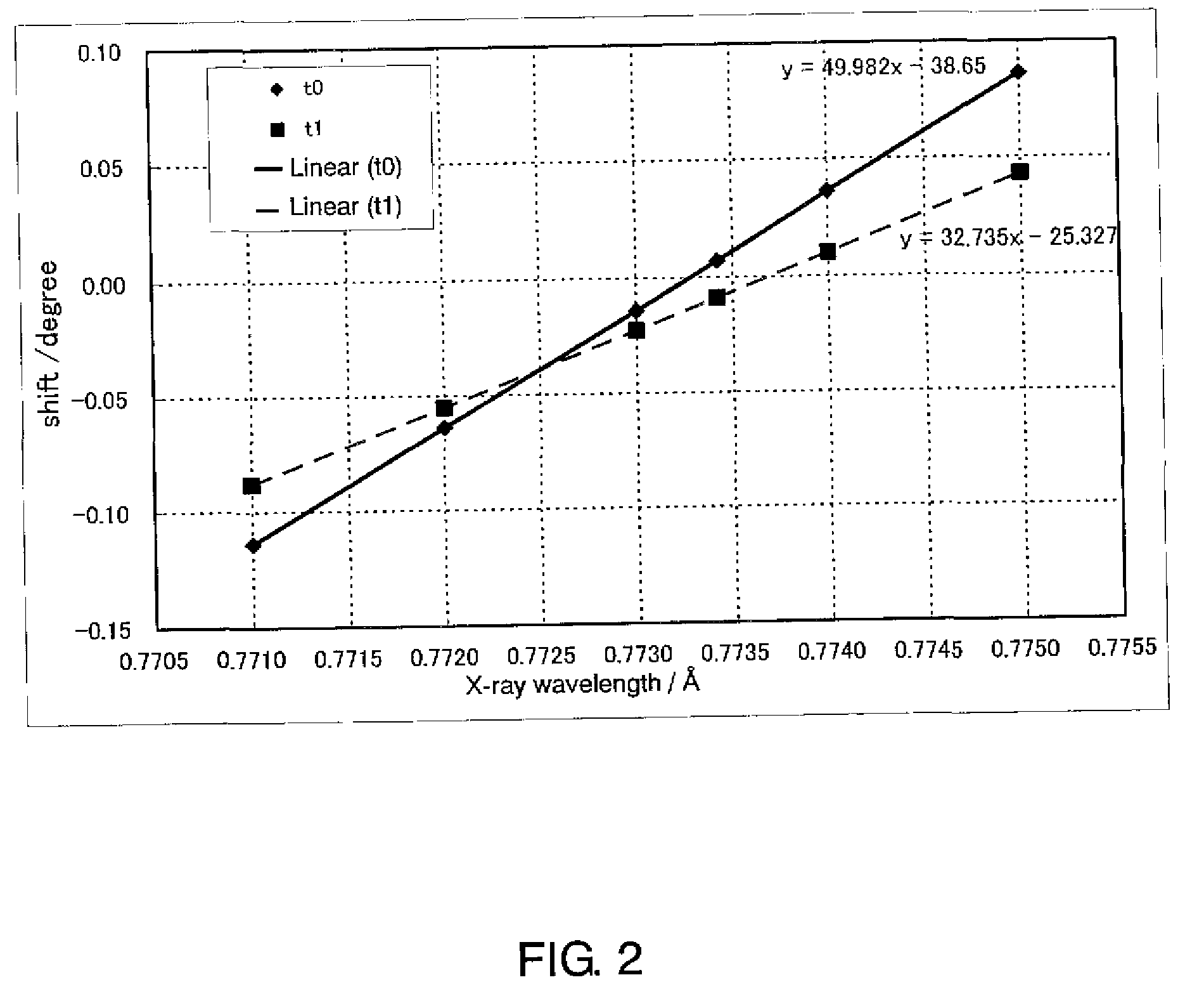
[0022]Moreover, in the present invention, a value of a linear coupling function s represented by a formula:

s=−11622+2043.07La+199.24L1−116.91L2

is 1 or less, when a lattice constant is La(Å), an interatomic distance between Al(2) and O(5) is L1(Å), and an interatomic distance between Al(1) and O(4) is L2(Å), which are obtained by an X-ray crystal structure analysis assuming that the aluminate...


PUM


Abstract

The present invention is a light-emitting device which is provided with a phosphor layer containing a blue phosphor, wherein the phosphor layer includes an aluminate phosphor, as the blue phosphor, that contains Ba, Sr, Eu, Mg, Al and O as constituting elements at an atom-number ratio Ba:Sr:Eu:Mg:Al:O=p:q:r:1:w:17 wherein 0.70≦p≦0.95, 0≦q≦0.15, 0.05≦r≦0.20, p+q+r≧1, and 9.8≦w≦10.5 are satisfied, and a value of a linear coupling function s represented by a formula:
s=−11622+2043.07La+199.24L1−116.91L2
is 1 or less, when a lattice constant is La(Å), an interatomic distance between Al(2) and O(5) is L1(Å), and an interatomic distance between Al(1) and O(4) is L2(Å), which are obtained by an X-ray crystal structure analysis assuming that the aluminate phosphor belongs to a space group P63/mmc.

Description

TECHNICAL FIELD[0001]The present invention relates to a light-emitting device that contains an aluminate phosphor as a blue phosphor in a phosphor layer.BACKGROUND ART[0002]As a blue phosphor of a light-emitting device such as a plasma display panel (PDP), an alkaline earth aluminate phosphor (hereinafter, this phosphor may be simply referred to as “aluminate phosphor”), which is activated with europium and is so-called BAM:Eu, such as BaMgAl10O17:Eu and (Ba,Sr)MgAl10O17:Eu, has been drawing attention. This is because the aluminate phosphor is superior in a property of emitting visible light under vacuum ultraviolet ray excitation to other blue phosphors.[0003]A phosphor layer of the PDP or the like has been produced by mixing a phosphor and a binder to prepare slurry, applying the slurry onto a surface of a substrate such as glass, and then baking the substrate.[0004]In the meanwhile, when the aluminate phosphor is used, a wavelength conversion efficiency greatly degrades over time...

Claims


Application Information

Patent Timeline
IPC IPC(8): H01J1/62H01J17/49H01J11/12H01J11/42
CPCC09K11/7734H01J1/63H01J11/42H01J11/12H01J61/44C09K11/08
Inventor SAKAI, MASAHIROSHIRAISHI, SEIGOZUKAWA, TAKEHIROOKUYAMA, KOJIROHIBINO, JUNICHISUGIMOTO, KAZUHIKO
Owner PANASONIC CORP
Why Eureka
Try Eureka