High intensity plasma lamp

a plasma lamp and high-intensity technology, applied in the direction of electric discharge lamps, basic electric elements, electrical appliances, etc., can solve the problems of bulb failure, deterioration and erode, short-arc lamps that have not tended to be long-lived, etc., and achieve unprecedented operating life expectancy

Inactive Publication Date: 2008-08-28
CERAVISION LTD
View PDF3 Cites 18 Cited by
  • Summary
  • Abstract
  • Description
  • Claims
  • Application Information

AI Technical Summary

Benefits of technology

[0012]In more specific aspects, the window may be a sapphire window. The invention greatly extends the operating life expectancy of the plasma lamp as compared with the prior art lamps which use quartz because the problems of quartz devitrification at high temperature and quartz gas permeability are eliminated.
[0015]Because the integration of the RF structure and the gas envelope permits the quartz bulb to be done away with entirely, plasma lamps according to the present invention enjoy an unprecedented operating life expectancy as compared with the prior art. This is so in part because the problems associated with the inability of the quartz bulb to withstand repeated heating and cooling are eliminated.
[0016]In addition, the integrated design of the present invention enables a much higher proportion of the radio wave radiation energy to be focused onto the gas fill. As a result, the plasma lamp according to the present invention is made much more efficient.

Problems solved by technology

Although a short arc lamp produces an intense light by maintaining an electric arc between two closely spaced electrodes, short arc lamps have not tended to be long-lived for at least two reasons.
First, the electrodes between which the arc is formed inevitably deteriorate and erode during operation, and ultimately this erosion leads to bulb failure as the bulb approaches and finally exceeds half brightness, an industry standard for the end of life of the bulb.
Second, short arc lamps conventionally employ an envelope or bulb made from a transparent material in order to contain the gas fill of the lamp.
Quartz bulbs, however, have several disadvantages that materially affect the life of the bulb.
Because quartz devitrifies at elevated temperatures, particularly when exposed to moisture, oils from finger prints, and other contaminates that are ever present in air pollution, quartz bulbs do not endure well when exposed to repeated heating and cooling inherent in lamp operation.
The result of exposure to these elements is that they tend to eventually discolor or crack causing lamp failure and limiting the useful life span of the lamp.
In addition, because quartz has a low thermal conductivity, the use of the quartz bulb limits the maximum operating temperature of the lamp, and, therefore, the maximum obtainable brightness from the short arc created between the electrodes.
Furthermore, quartz is partially permeable so that certain gases contained within the bulb gas mixture tend to slowly diffuse out of the bulb envelope during operation of the bulb, and other gases tend to slowly diffuse into the bulb during cool-down, thus diluting the gas constituents and changing the bulb operating properties.
Ultimately, this diffusion causes the lamp to fail.
Although there are no electrodes to fail in the case of a plasma lamp, the transparent bulb that is conventionally used to contain the gas is also typically made of quartz and has similar disadvantages discussed above in connection with the arc lamp because of the high operating temperatures involved.
However, such mechanical arrangements are complex, expensive, have moving parts that fail, and occupy space which is often a scarce resource in the intended application for the lamp.
In addition, the presence of these mechanical arrangements tends to compromise the ability to collect the light generated by the lamp, thereby reducing efficiency.
The need for such a separate coupling mechanism is another problem with the RF plasma lamp because inefficiency of the coupling correspondingly constrains the overall efficiency of the plasma lamp itself.
In practice this approach may lead to a power loss of as high as 60% because of coupling inefficiencies.
In addition, the resulting lamp structure is not physically compact because the RF structure is separate from the bulb.
Again, however, the resulting structure lacks integration and compactness because the RF structure is separate from the bulb.

Method used


Image

  • High intensity plasma lamp
  • High intensity plasma lamp
  • High intensity plasma lamp

Examples


first embodiment

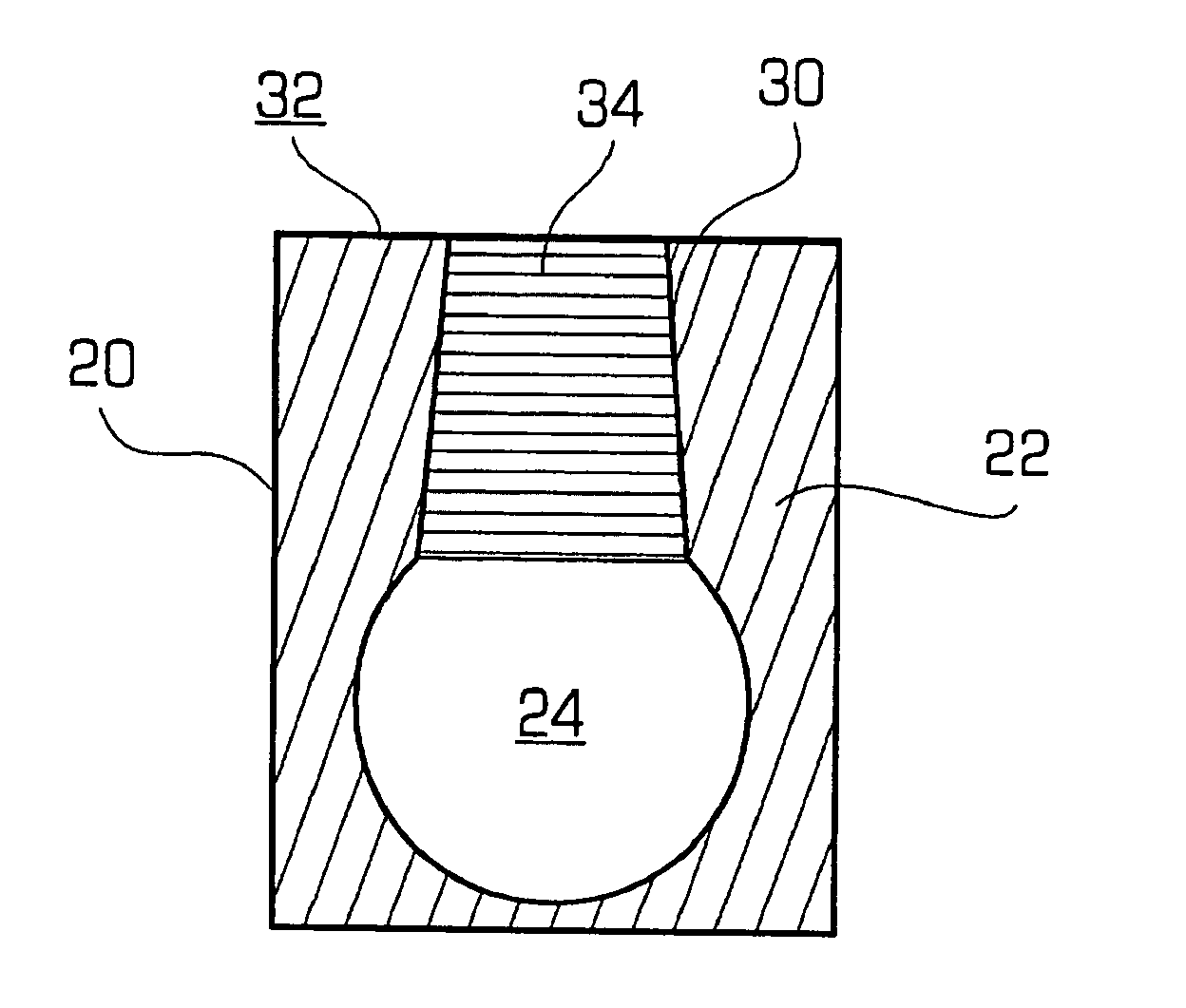
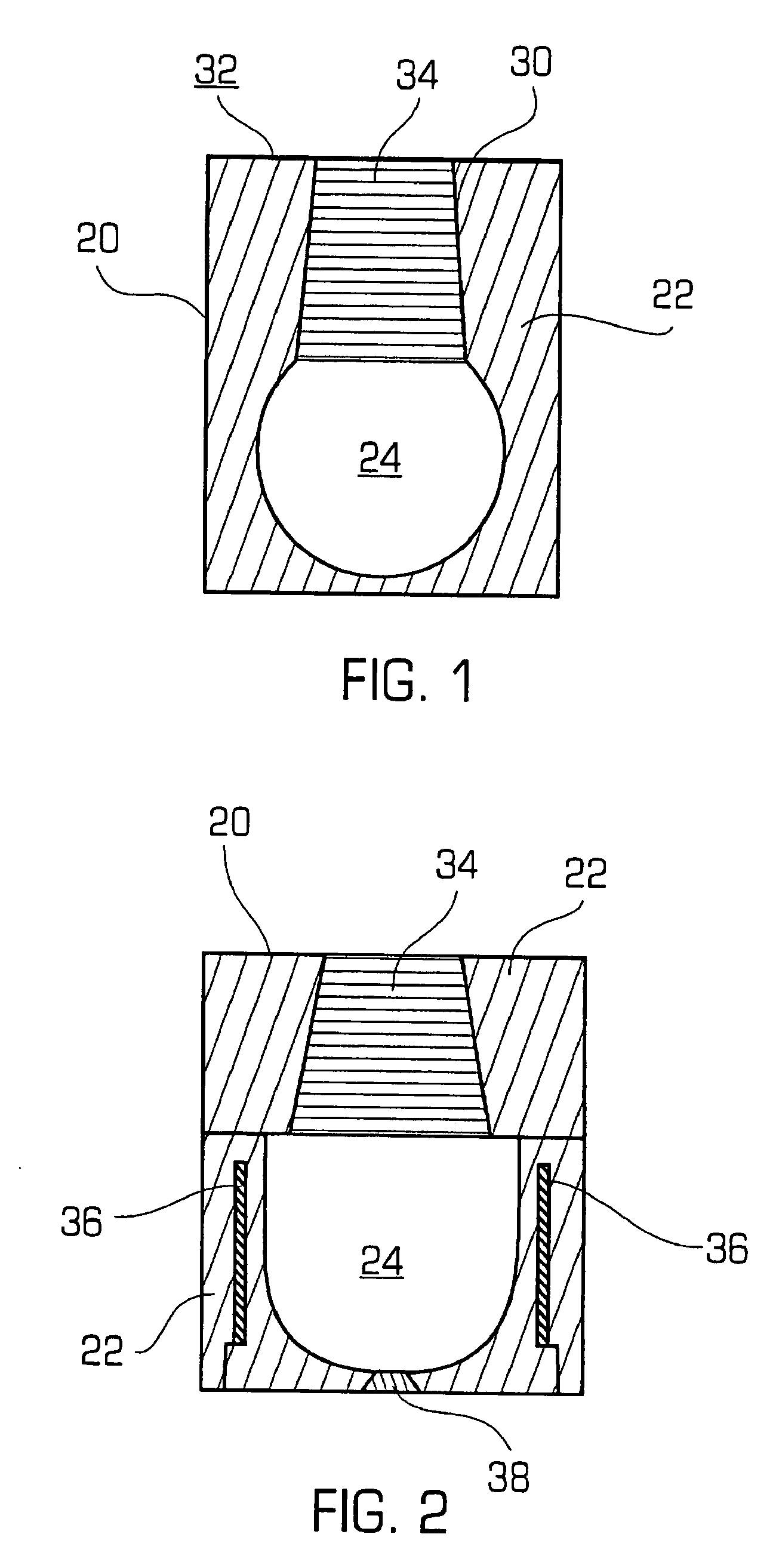
[0025]FIG. 1 shows an improved light source in accordance with the invention. The light source may be a plasma lamp comprising a gas housing 20 preferably formed from a ceramic material 22, as will be described below, with an interior cavity or chamber 24 for containing gas. The housing may generally be rectilinear or cubic, and the chamber may be spherical. A channel 30 may connect the chamber to an exterior surface 32 of the housing. The channel 30 may be made of light transmissive material, preferably of sapphire in order to form a window 34 for emitting visible light from the chamber. The window preferably has a generally tapered, conical shape; i.e., a frusto-conical shape. The sapphire window seals the chamber to contain the gas, while affording an exit for the light produced by the plasma discharge.

[0026]Sapphire is preferred for the window since it is less gas permeable than quartz, for example, and better withstands the heat cyclings and high temperatures associated with la...

second embodiment

[0031]FIG. 2 shows a lamp in accordance with the invention which is somewhat similar to FIG. 1 except that the gas housing has an integrated RF energy structure. In FIG. 2, the elements are designated similarly to FIG. 1, using like reference numerals for like elements. The gas fill chamber 24 may be housed in a gas housing 20 preferably comprising a ceramic material 22 and provided with a light transmissive window 34, preferably of a tapered rod of sapphire and a fill plug 38 as previously described. In this embodiment, an RF energy structure such as one or more coils 36 may be formed within the ceramic housing. The coils 36 function to inductively couple radio wave radiation energy to the gas fill in chamber 24 in order to create the plasma discharge. In this way, the RF structure of the plasma lamp that is active with radio wave energy is integral with the ceramic housing 20 that contains the plasma gas fill. This integration of the RF structure of the plasma lamp and the gas hou...

third embodiment

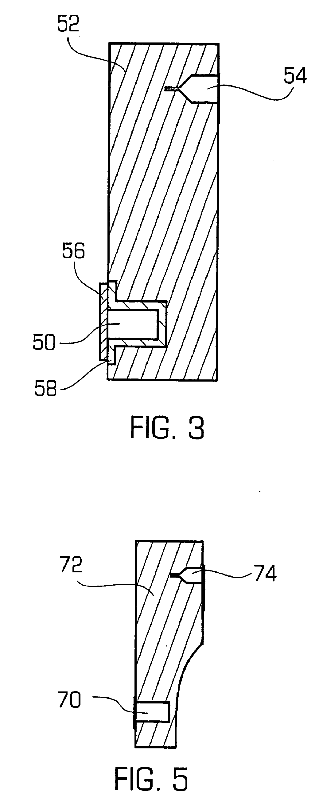
[0033]FIG. 3 shows a lamp in accordance with the invention which integrates both the gas housing and an RF energy source within the same structure. A gas housing 50 for the gas fill may be formed so as to be integral with a waveguide 52 which preferably comprises a ceramic structure having a substantially rectangular cross-section. Because no separate bulb is used, the housing 50 and waveguide 52 comprise a single, integrated structure. A source of radio wave radiation 54 may be disposed within the ceramic structure, for example, near one end of the waveguide. The RF source 54 may be an RF antenna, a probe, or the like for introducing RF energy into the waveguide. The gas housing 50 may be located near the other end of the waveguide, for example. As shown, the gas housing may further include a light transmissive window 56 connected to the end wall of the housing. The window is preferably made from sapphire.

[0034]The dimensions of the waveguide and the locations of the RF source and ...


PUM


Abstract

A plasma lamp is provided having an integrated dielectric waveguide structure having a body, a gas housing formed within the body and having an aperture formed at a first outer surface of the body, a fill mixture disposed within the gas housing, and a probe operatively coupled to the body so that microwave energy supplied to the fill mixture forms a plasma that emits high intensity light.

Description

RELATED U.S. APPLICATION DATA[0001]This application is a continuation application of U.S. patent application Ser. No. 09 / 818,092, filed Mar. 26, 2001, which claims the benefit of the following U.S. Provisional Applications: U.S. Provisional Applications Nos. 60 / 192,731 filed Mar. 27, 2000; 60 / 224,059 filed Aug. 9, 2000; 60 / 224,060 filed Aug. 9, 2000; 60 / 224,061 filed Aug. 9, 2000; 60 / 224,298 filed Aug. 10, 2000; 60 / 224,503 filed Aug. 10, 2000; 60 / 224,290 filed Aug. 10, 2000; 60 / 224,291 filed Aug. 10, 2000; 60 / 224,257 filed Aug. 10, 2000; 60 / 224,289 filed Aug. 10, 2000; 60 / 224,866 filed Aug. 11, 2000; 60 / 224,961 filed Aug. 11, 2000; 60 / 224,617 filed Aug. 11, 2000; and 60 / 234,415 filed Sep. 21, 2000; 60 / 241,198 filed Oct. 17, 2000; 60 / 246,662 filed Nov. 7, 2000; 60 / 253,261 filed Nov. 27, 2000; 60 / 254,727 filed Dec. 11, 2000; 60 / 262,537 filed Jan. 17, 2001; 60 / 262,536 filed Jan. 17, 2001; 60 / 262,538 filed Jan. 17, 2001; 60 / 265,945 filed Feb. 1, 2001 and 60 / 270,857 filed Feb. 21, 2001.[...

Claims


Application Information

Patent Timeline
Patent Type & Authority Applications(United States)
IPC IPC(8): H01J61/30H01J65/04
CPCH01J65/048H01J65/044
Inventor GUTHRIE, CHARLESSANDBERG, EDMUNDWILSON, DONALDPRIOR, GREGSMOLER, DAVID
Owner CERAVISION LTD
Why Eureka
Try Eureka