Apparatus and method for driving synchronous motor
Active Publication Date: 2008-08-28
HITACHI POWER SEMICON DEVICE +1
View PDF11 Cites 26 Cited by
Summary
Abstract
Description
Claims
Application Information
AI Technical Summary
This helps you quickly interpret patents by identifying the three key elements:
Problems solved by technology
Method used
Benefits of technology
Benefits of technology
[0011]In addition, the conventional synchronous motor drive apparatus must be provided with a circuit for detecting the data on the currents from the power source and therefore cannot enjoy a simple structure and a low cost.
[0013]One object of this invention is to provide an apparatus and a method for driving a synchronous motor which can be operated with low mechanical noise and high efficiency.
[0014]Another object of this invention is to provide an apparatus and a method for driving a synchronous motor which is built inexpensively, does not depend on the motor parameters, and can be used in a wide variety of applications.
[0019]According to another embodiment of this invention, an apparatus or a method for driving a synchronous motor can be realized which can be operated with high efficiency and low mechanical noise, by maintaining the phase difference between each phase current and the corresponding magnetic position sensorsignal at a preset value and by so controlling the rotational speed of the synchronous motor as to approach the motor speed command value.
[0020]According to still another embodiment of this invention, an apparatus or a method for driving a synchronous motor can be realized which is of inexpensive structure, has a universal applicability without dependence on the motor characteristic and is operable with high efficiency, by making variable the target value for the phase difference between each phase current and the corresponding magnetic position sensorsignal.
Problems solved by technology
Accordingly, if the amplitudes of the voltages supplied to the motor are calculated from the data on the currents from the power source and on the torque commands, such voltages are not optimal so that the motor speed fluctuates, which leads to the generation of mechanical noise.
In addition, the conventional synchronous motor drive apparatus must be provided with a circuit for detecting the data on the currents from the power source and therefore cannot enjoy a simple structure and a low cost.
Further, since the magnitude of the reluctance torque depends on the motor parameters (e.g. resistances and inductances of windings, and back EMF constant), reduction in efficiency is incurred.
Method used
Image
Click on the blue label to locate the original text in one second.
Reading with bidirectional positioning of images and text.
Examples
embodiment 1
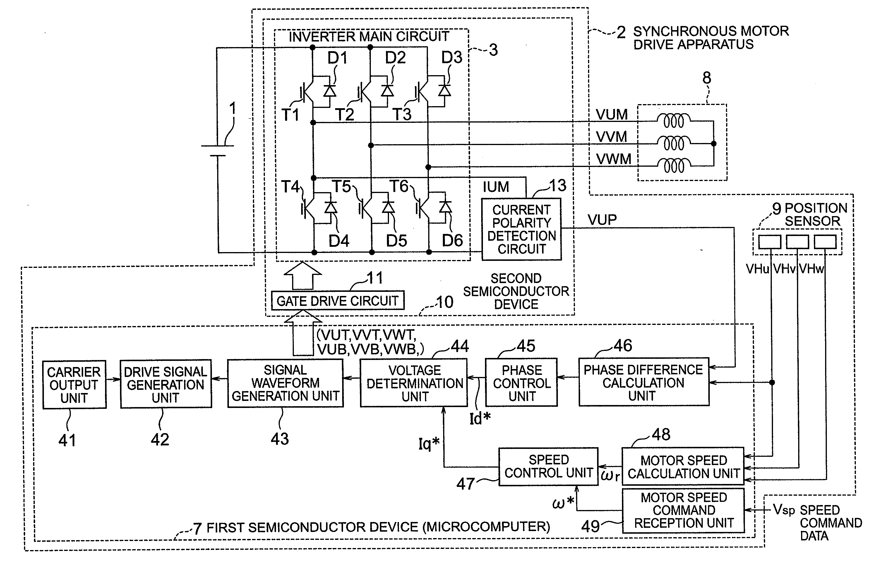
[0054]FIG. 1 shows in general block diagram an apparatus for driving a synchronous motor as a first embodiment of this invention. This synchronous motor drive apparatus 2 can be suitably applied as a drive apparatus for a fan motor used in, for example, the outdoor unit of an air conditioner.
(Description of Drive Apparatus as a Whole)
[0055]The main circuit in FIG. 1 will first be described. A DC power source 1 supplies DC power to a synchronous motor drive apparatus 2. The voltage of the DC power is a high voltage of about 141˜450 volts and fed from a battery or a converter available in the market which is used to commutate and smooth the commercial AC power.
[0056]An inverter main circuit 3 consists of six switching elements T1˜T6. The switching elements T1 and T4 are connected in series with each other, the switching elements T2 and T5 are connected in series with each other, and the switching elements T3 and T6 are connected in series with each other. The three series circuits of ...
embodiment 2
[0166]FIG. 23 shows in general block diagram an apparatus for driving a synchronous motor as a second embodiment of this invention. In FIG. 23, the same components as shown in FIG. 1 are indicated by the same reference numerals. Only different components are described below.
[0167]The synchronous motor drive apparatus shown in FIG. 23 differs from that shown in FIG. 1 in the additional provision of a phase difference target value calculation unit 50.
[0168]FIG. 24 is a flow chart for the interruption procedure for position detection performed in the second embodiment of this invention. FIG. 24 is the same as FIG. 12 except the addition of Step 241 of calculating phase difference target value.
[0169]FIG. 25 is an example of the graphic representation illustrating the relationship between the phase difference target value and the value of the detected speed, observed in the case where the phase difference target value is varied in accordance with the value of the detected speed.
[0170]In ...
embodiment 3
[0174]FIG. 26 shows in general block diagram an apparatus for driving a synchronous motor as a third embodiment of this invention. In FIG. 26, the same components as those shown in FIG. 1 are indicated by the same reference numerals. Only different components are described below.
[0175]The synchronous motor drive apparatus shown in FIG. 26 differs from that shown in FIG. 1 in the additional provision of a phase difference target value input unit 51.
[0176]The phase difference target value input unit 51 receives and holds the phase difference target value θih* preset outside the microcomputer. The phase difference target value input unit 51, after having held the received phase difference target value, operates in the same manner as described with the first embodiment detailed above, and therefore the operation of the unit 51 is omitted here. Further, the phase difference target value calculation unit 50 for the embodiment 2 may be used with the phase difference target value input unit...
PUM
Abstract
The synchronous motor driving apparatus including position sensors provided in the synchronous motor, a current polarity detection circuit for detecting the polarities of the currents in the respective phase windings of the synchronous motor, an inverter driving the synchronous motor, a motor speed calculation unit calculating the rotational speed of the synchronous motor depending on the output signals from the position sensors, a speed control unit outputting a first voltage adjusting component (q-axis current command value Iq*) to cause the rotational speed of the synchronous motor to approach a speed command value and a phase control unit outputting a second voltage adjusting component (d-axis current command value Id*) to cause the phase differences between the phases of the position sensor signals and of the currents in the respective phase windings of the synchronous motor to become a predetermined value.
Description
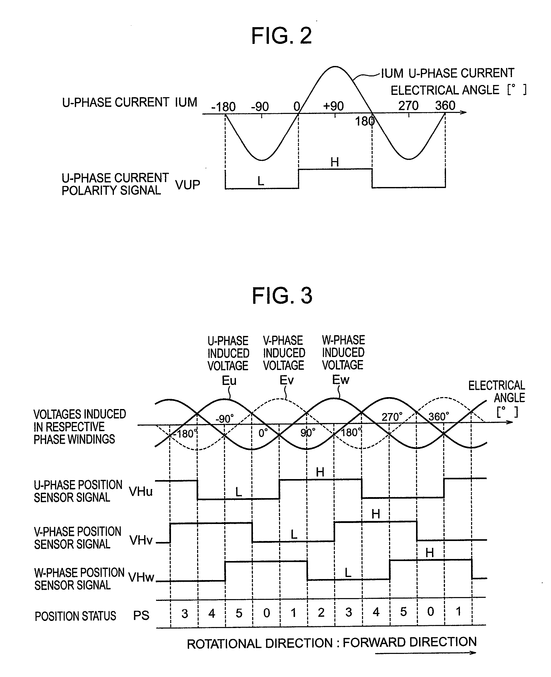
BACKGROUND OF THE INVENTION[0001]This invention relates to an apparatus and a method for driving a synchronous motor.[0002]Synchronous motors have recently been used as fan motors for use with air conditioners and hot water suppliers, which are well adapted for the control of rotational speeds over a wide range, the economy of consumed electric energy and the suppression of mechanical noise. Also, such synchronous motors have been driven by suitable motor drive apparatuses.[0003]Usually, Hall ICs (integrated circuits) as position sensors having a simple structure and being most inexpensive are incorporated in a synchronous motor. The Hall IC detects the positions of the magnetic poles of the synchronous motor so that the synchronous motor is driven by applying appropriate voltages across its windings accordingly. Further, the polarities of currents flowing though the windings of the synchronous motor are detected. The phase difference obtained from the data on the current polarities...
Claims
Application Information
Patent Timeline
Application Date:The date an application was filed.
Publication Date:The date a patent or application was officially published.
First Publication Date:The earliest publication date of a patent with the same application number.
Issue Date:Publication date of the patent grant document.
PCT Entry Date:The Entry date of PCT National Phase.
Estimated Expiry Date:The statutory expiry date of a patent right according to the Patent Law, and it is the longest term of protection that the patent right can achieve without the termination of the patent right due to other reasons(Term extension factor has been taken into account ).
Invalid Date:Actual expiry date is based on effective date or publication date of legal transaction data of invalid patent.

