Control system and method for a universal power conditioning system

a control system and power conditioning technology, applied in power conversion systems, climate sustainability, electrical equipment, etc., can solve problems such as affecting the output power quality, steady-state error in ac power output can be decomposed, and fuel cell power conditioning output suffers from steady-state error problems

Active Publication Date: 2008-08-28
VIRGINIA TECH INTPROP INC
View PDF13 Cites 207 Cited by
  • Summary
  • Abstract
  • Description
  • Claims
  • Application Information

AI Technical Summary

Benefits of technology

[0010]In order to achieve the above and other objects, a new current loop controller is disclosed for a single-phase grid-tie power conditioning system that can be used under standalone or grid-tie mode. The current loop controller achieves admittance compensation to eliminate the steady-state error problem described above by using an inductor-capac

Problems solved by technology

The fuel cell power conditioning output, however, suffers from a steady-state error problem, as seen in most single-phase inverters.
This steady-state error in AC power output can be decomposed into a magnitude offset, a phase offset, and a current distortion.
While a small amplitude offset may not be a concern for utility applications, a phase offset and waveform distortions can significantly affect the output power quality so as to fail to meet power quality standards.
A major cause of the inverter output steady-state error has long been identified as insufficient controller loop gain at a fundamental frequency such as 50 Hz or 60 Hz or at the harmonic frequencies.
Use of a P

Method used


Image

  • Control system and method for a universal power conditioning system
  • Control system and method for a universal power conditioning system
  • Control system and method for a universal power conditioning system

Examples


experimental verification

[0069

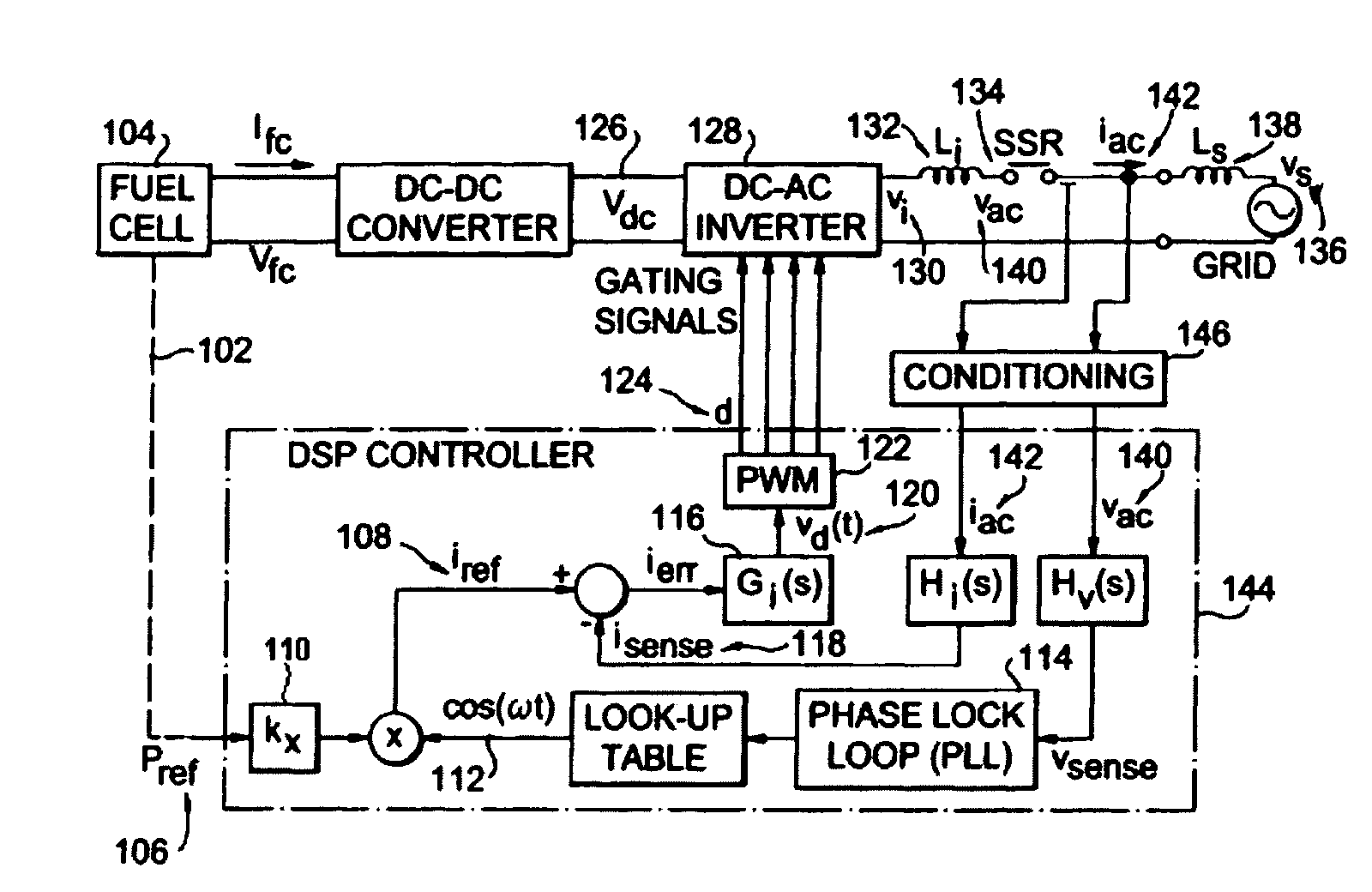
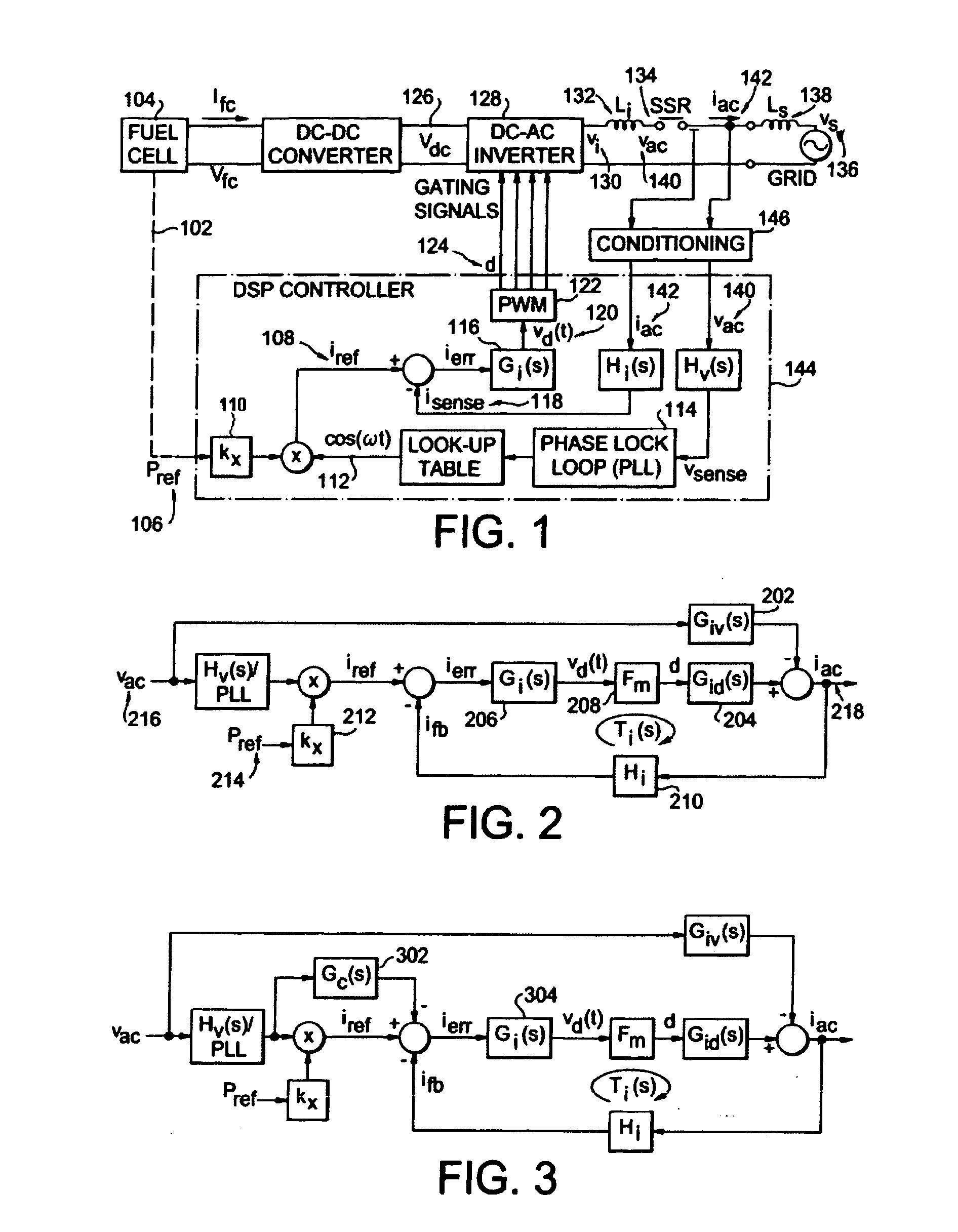
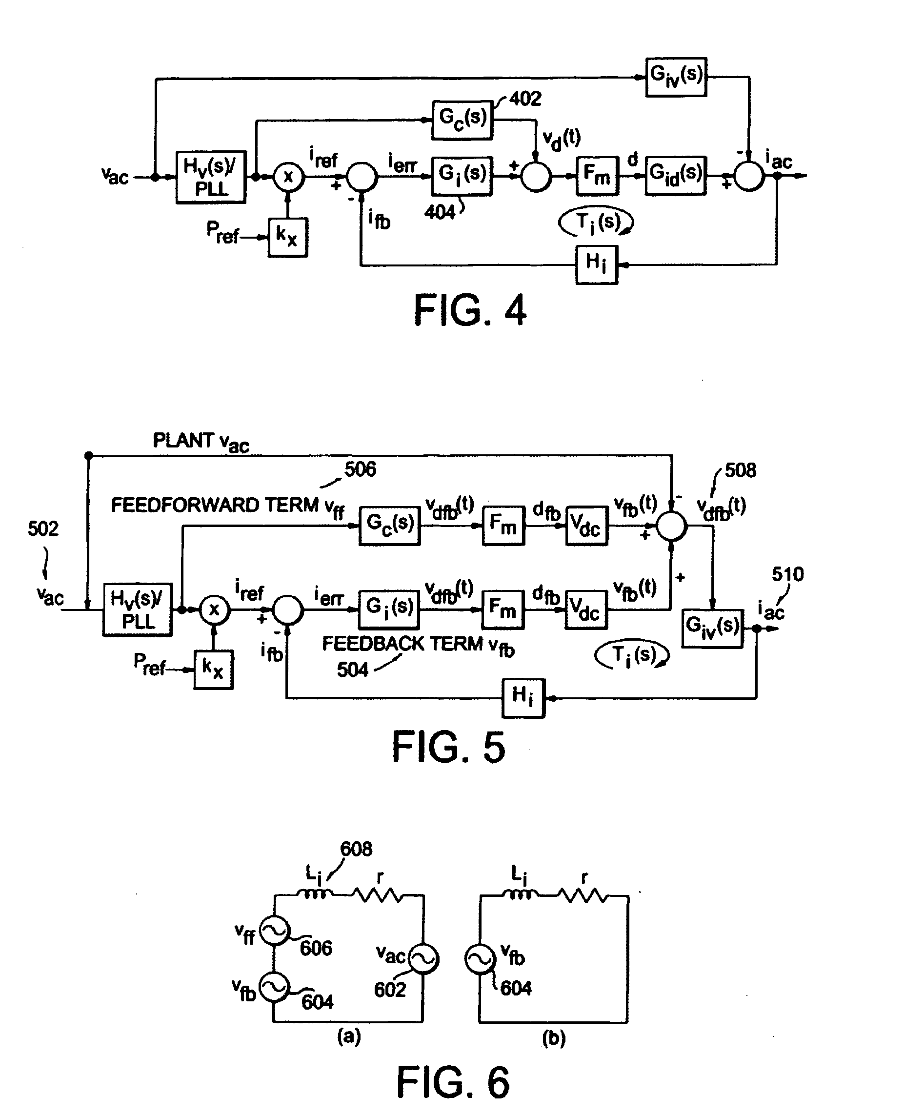
[0070]A PCS prototype, shown in FIG. 12, comprising of a DC-DC converter to boost the fuel cell voltage from about 25V to 400V and a dc-ac inverter that produces 208 Vrms ac output for the grid connection was tested with a solid oxide fuel cell (SOFC) simulator 1202, which mimics an actual low-voltage SOFC that has a stack of 36 cells operating at 1000° C. FIG. 12 shows a photograph of the test setup with the PCS prototype 1204 and associated instrumentation. A precision current shunt 1206 is used to calibrate the current measurement. The front panel of the case is open to show the DSP board 1208 which, in the prototype embodiment, is an in-house developed TMS320F2812 control board containing all necessary interfaces and signal conditioning circuits.

[0071]FIG. 13A shows the start-up waveform of the grid-tie inverter operation. The SSR logic 1302 may be commanded on 1304 at any time, but the actual switch-on point is at the zero crossing 1306. The PWM logic signal 1308 will not ...


PUM


Abstract

A new current loop control system method is proposed for a single-phase grid-tie power conditioning system that can be used under a standalone or a grid-tie mode. This type of inverter utilizes an inductor-capacitor-inductor (LCL) filter as the interface in between inverter and the utility grid. The first set of inductor-capacitor (LC) can be used in the standalone mode, and the complete LCL can be used for the grid-tie mode. A new admittance compensation technique is proposed for the controller design to avoid low stability margin while maintaining sufficient gain at the fundamental frequency. The proposed current loop controller system and admittance compensation technique have been simulated and tested. Simulation results indicate that without the admittance path compensation, the current loop controller output duty cycle is largely offset by an undesired admittance path. At the initial simulation cycle, the power flow may be erratically fed back to the inverter causing catastrophic failure. With admittance path compensation, the output power shows a steady-state offset that matches the design value. Experimental results show that the inverter is capable of both a standalone and a grid-tie connection mode using the LCL filter configuration.

Description

REFERENCE TO RELATED APPLICATION[0001]The present application claims the benefit of U.S. Provisional Patent Application No. 60 / 891,118, filed Feb. 22, 2007, whose disclosure is hereby incorporated by reference in its entirety into the present disclosure.FIELD OF THE INVENTION[0002]The present invention is directed to a current loop control system and in particular to a current loop control system for a power conditioning system.DESCRIPTION OF RELATED ART[0003]Fuel cell outputs tend to have a slow time constant due to the use of balance-of-plant (BOP) controllers, and thus it is more suitable for a grid-tie system where the load dynamic can be better managed with slow current ramps. The fuel cell power conditioning output, however, suffers from a steady-state error problem, as seen in most single-phase inverters. This steady-state error in AC power output can be decomposed into a magnitude offset, a phase offset, and a current distortion. While a small amplitude offset may not be a c...

Claims


Application Information

Patent Timeline
IPC IPC(8): H02M1/12
CPCH02J3/38Y02B70/1441H02M7/53871Y02B70/10
Inventor LAI, JIH-SHENGPARK, SUNG YEULCHEN, CHIEN-LIANG
Owner VIRGINIA TECH INTPROP INC
Why Eureka
Try Eureka