
Unstable resonator with variable output coupling

a variable output and resonator technology, applied in the direction of optical resonator shape and construction, laser details, active medium materials, etc., can solve the problems of requiring the utilization of an expensive and extensive set of cavity optics, unable to meet the normal compatibility of modest to short lengths of gain media, and unable to achieve a practical variable output coupling technology, etc. , to achieve the effect of avoiding electrode edge effects, simple and straightforward manner, and exploring the optimal output coup

Inactive Publication Date: 2008-08-28
COHERENT INC
View PDF11 Cites 9 Cited by
  • Summary
  • Abstract
  • Description
  • Claims
  • Application Information

AI Technical Summary

Benefits of technology

[0015]In accordance with the concepts of the present invention, if one uses a relatively inexpensive third mirror in a new folded hybrid unstable resonator configuration, the optimum output coupling for a given laser design can be explored quickly and easily with a minimum of intracavity mirror alignment. No changes in either the radii of curvature of the three cavity optics or their spacing are required for this exploration. Furthermore, in addition to teaching a means of purposefully and systematically introducing mirror edge effects or avoiding electrode edge effects altogether, the present invention also provides that output beams of different width can be advantageously explored in a relatively simple and straightforward manner. Likewise, the invention provides that higher geometric magnification cavity designs may be made compatible with low diffraction output coupling in a configuration using only three totally reflecting optics.

Problems solved by technology

However, for all of the advantages enjoyed by the technology disclosed in the above-cited '639, '048 and '028 patents, including utilization of only two all-reflecting cavity optics and the extraction of a filled in output beam, this technology can only achieve a practical variable output coupling by changing a minimum of both cavity mirror radii and the width of the mirror at the output coupling end of the resonator.
Because the two intra-cavity optics in a prior art high power output RF excited CO2 hybrid unstable resonator system require water cooling, they are very expensive.
As a consequence, this means that the determination of the optimum output coupling for a given length and width of active medium involves performing a series of detailed and careful experiments and requires utilization of an expensive and extensive set of cavity optics.
Unfortunately, higher geometric magnification and modest to short lengths of gain media are not normally compatible because this combination will result in overcoupling the gain medium of the laser.
In this case, taking advantage of a higher magnification resonator comes at the expense and complication associated with four curved intracavity optics.
To realize the benefits of a higher geometric magnification in this case obviously requires the use of a very expensive, curved, partially transmitting optic and the need to use a high reflectivity intracavity beam deflection optic to direct the intracavity flux to the partial reflector.
4 regarding the problem of easily achieving “adjustable diffraction output coupling” in hybrid unstable resonators has not been systematically addressed or solved.

Method used


Image

  • Unstable resonator with variable output coupling
  • Unstable resonator with variable output coupling
  • Unstable resonator with variable output coupling

Examples


Embodiment Construction

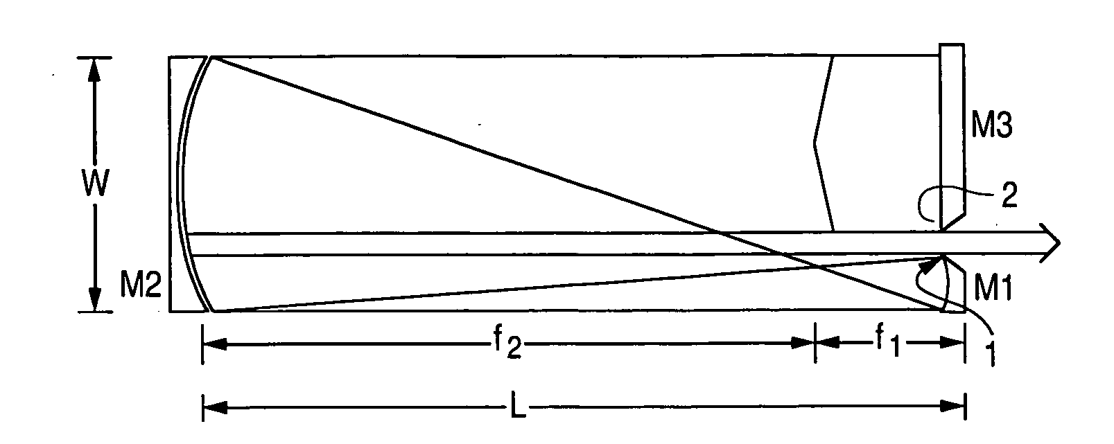
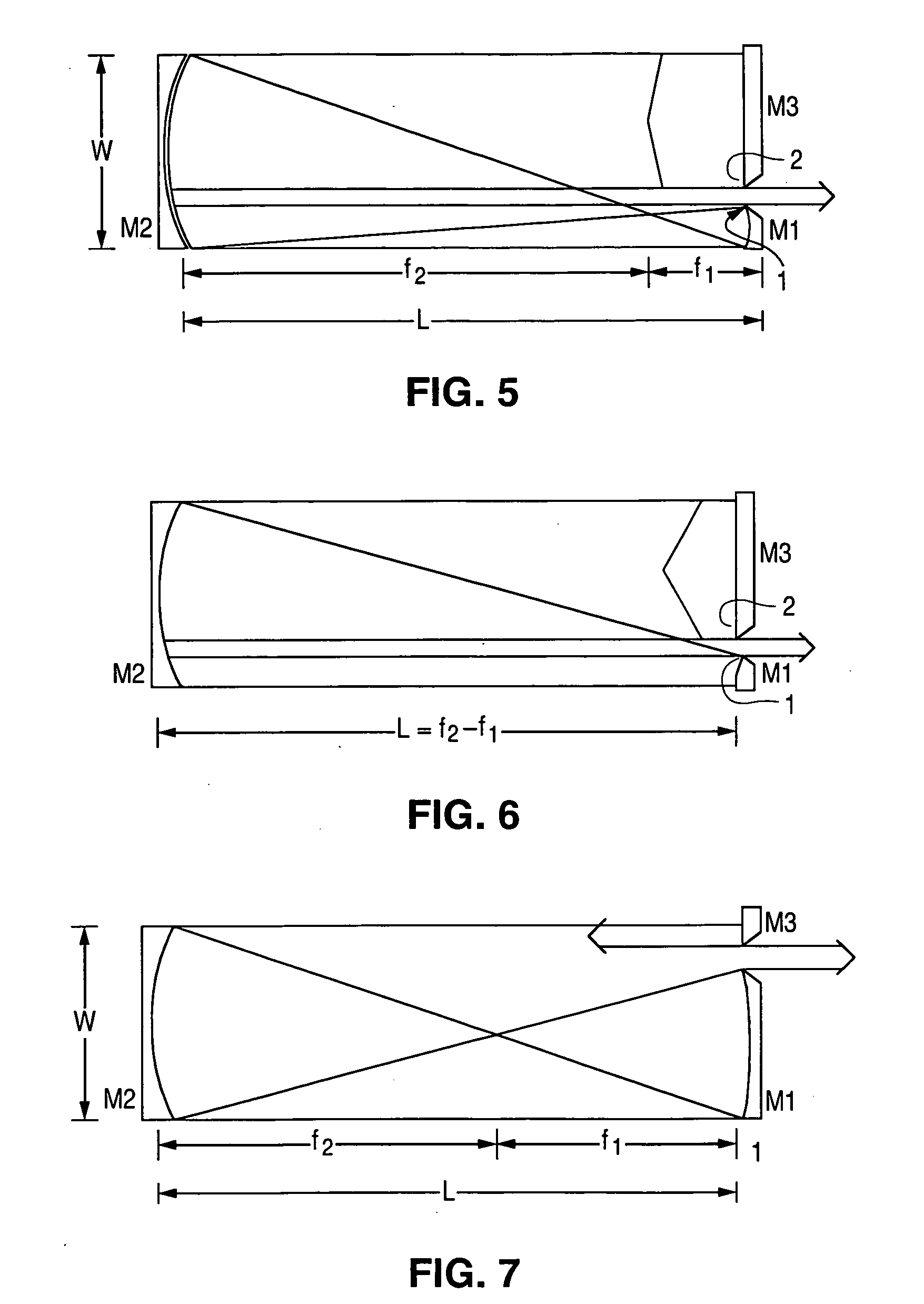
[0043]FIG. 5 shows a folded three mirror embodiment of a hybrid unstable resonator in accordance with the concepts of the present invention as viewed perpendicular to the longer transverse side of the gain medium cross section. The FIG. 5 depiction emphasizes a high geometric magnification, negative branch confocal pair communicating with a comparatively large aperture planar cavity end mirror. This configuration addresses a combination of high geometric magnification and modest to low fractional output coupling. Also depicted in FIG. 5 are two features, designated by reference numerals 1 and 2, positioned at the upper edge of mirror M1 and the lower edge of mirror M3, respectively. Feature 1 on mirror M1 is a contoured edge nominally taught as part of prior art technology as the element responsible for radiation reflected from the forward or expanding wave of a hybrid unstable resonator that acts as the source of radiation initially feeding the reverse wave of such cavities. In acc...


PUM


Abstract

Through the use of a relatively inexpensive third mirror on a novel folded hybrid unstable resonator configuration, the optimum output coupling for a given laser design can be explored quickly and easily with a minimum of intracavity mirror alignment. No changes in either the radii of curvature of the three cavity optics or their spacing are required for this exploration. In addition to providing techniques for purposefully and systematically introducing mirror edge effects or avoiding edges effects altogether, the invention provides that output beams of different width can be advantageously explored in a relatively simple and straightforward manner. The invention provides that higher geometric magnification cavity designs may be made compatible with low diffraction output coupling in a configuration that uses only three totally reflecting optics.

Description

PRIORITY CLAIM[0001]This application claims priority from U.S. Provisional Application No. 60 / 902,975, filed Feb. 23, 2007, and titled “Unstable Resonator with Variable Output Cooling.” Provisional Application No. 60 / 902,975 is hereby incorporated by reference herein in its entirety.FIELD OF THE INVENTION[0002]The present invention relates generally to carbon dioxide (CO2) slab lasers and, in particular, to a folded hybrid unstable resonator configuration for a CO2 slab laser that facilitates quick and easy exploration of the optimum coupling for a given laser design with a minimum of intra-cavity mirror alignment.BACKGROUND OF THE INVENTION[0003]The worldwide market for high power, sealed-off, CO2 lasers continues to expand because of the growing need for improvements in applications like hole drilling, marking, cutting and scribing in ceramic and other common industrial materials. Driving this market is the need for lower cost, compact lasers with output powers in the range of 500...

Claims


Application Information

Patent Timeline
Patent Type & Authority Applications(United States)
IPC IPC(8): H01S3/00
CPCH01S3/0315H01S3/2232H01S3/0818
Inventor CHENAUSKY, PETER P.LAUGHMAN, LANNYMUELLER, ERIC R.NEWMAN, LEON A.SEGUIN, VERNON A.SHACKLETON, CHRISTIAN J.
Owner COHERENT INC
Learn More