Apparatus for Plasma-Enhanced Chemical Vapor Deposition (Pecvd) of an Internal Barrier Layer Inside a Container, Said Apparatus Including a Gas Line Isolated by a Solenoid Valve

a technology apparatus, which is applied in the direction of chemical vapor deposition coating, ion implantation coating, coating, etc., can solve the problems of negative impact on time t, and achieve the effect of reducing the volume of air that needs to be expelled, reducing the time t1, and reducing the time t0 a littl

Inactive Publication Date: 2008-08-28
SIDEL PARTICIPATIONS SAS
View PDF8 Cites 38 Cited by
  • Summary
  • Abstract
  • Description
  • Claims
  • Application Information

AI Technical Summary

Benefits of technology

[0030]In accordance with the invention, by means of the presence of the solenoid valve immediately upstream from the injector, the volume of air that needs to be expelled on injecting the precursor gas is reduced considerably. The solenoid valve, which is in the closed position while the container is being removed, limits the amount of air that flows back up into the injector by isolating the feed duct, which is still filled with pressurized precursor gas. It is thus possible to reduce the time t1 to a few tenths of a second (in practice in the range 0.2 s to 0.3 s), in addition to reducing the time t0 a little.

Problems solved by technology

In addition, while the precursor gas is being injected into the container, said precursor gas must travel along the feed duct before it reaches the container and serves to sweep said container, which has a negative impact on the time t1.

Method used


Image

  • Apparatus for Plasma-Enhanced Chemical Vapor Deposition (Pecvd) of an Internal Barrier Layer Inside a Container, Said Apparatus Including a Gas Line Isolated by a Solenoid Valve
  • Apparatus for Plasma-Enhanced Chemical Vapor Deposition (Pecvd) of an Internal Barrier Layer Inside a Container, Said Apparatus Including a Gas Line Isolated by a Solenoid Valve
  • Apparatus for Plasma-Enhanced Chemical Vapor Deposition (Pecvd) of an Internal Barrier Layer Inside a Container, Said Apparatus Including a Gas Line Isolated by a Solenoid Valve

Examples


Embodiment Construction

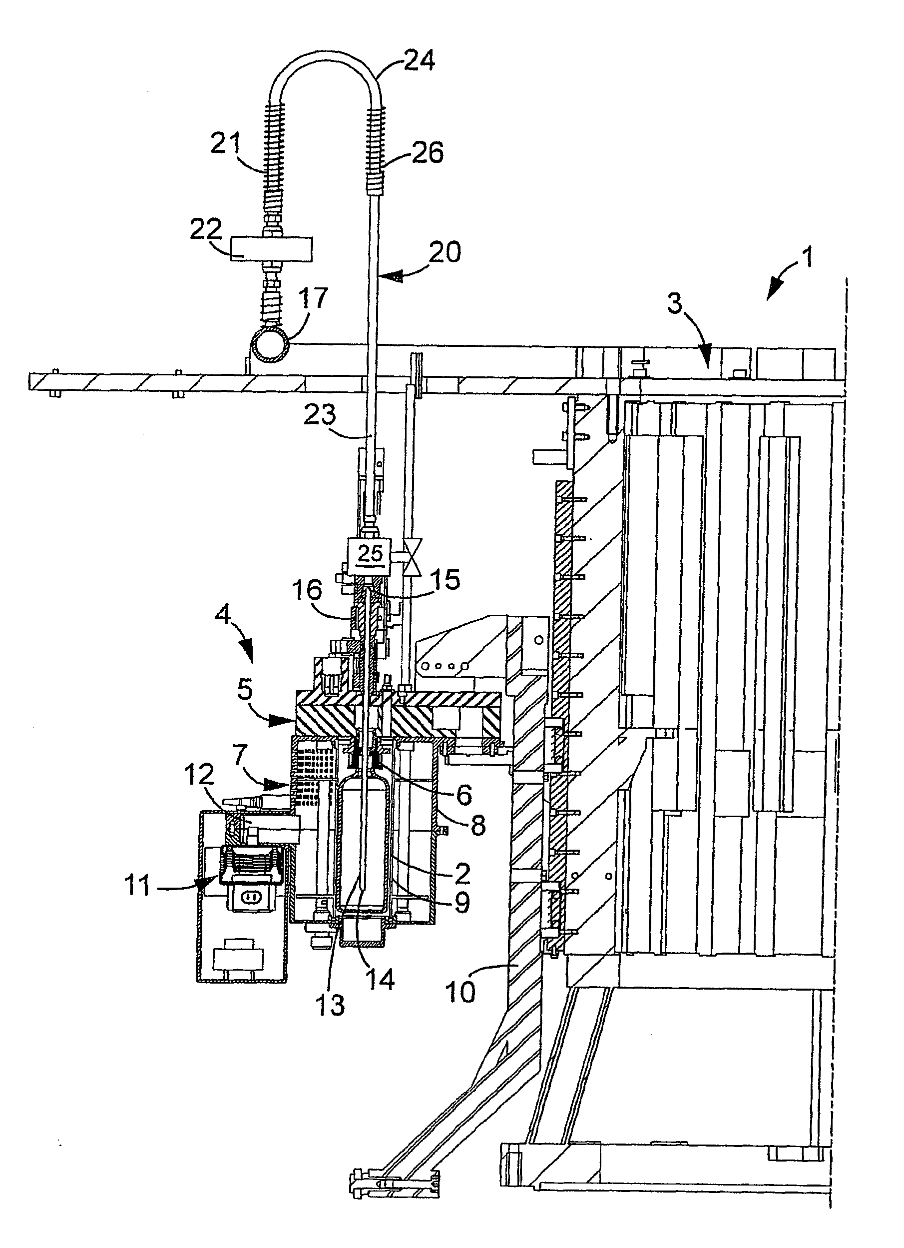
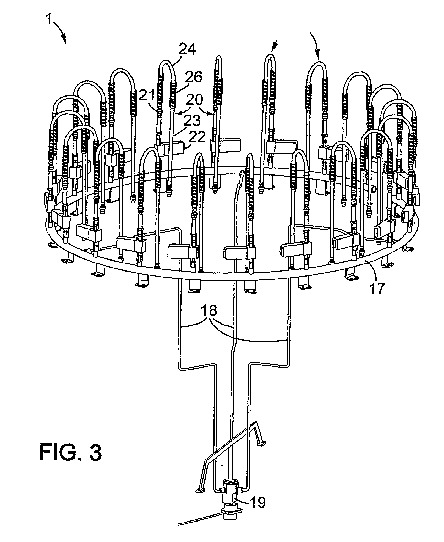
[0037]FIGS. 3 to 5 show a machine 1 for depositing respective thin layers of barrier-effect material by plasma-enhanced chemical vapor deposition (PECVD) on the inside walls of containers 2, such as bottles, one of which is shown in FIGS. 4 and 5.

[0038]This machine 1 comprises a carrousel 3, on which a plurality of processing units 4 are mounted, inside each of which the PECVD is performed on a respective container 2.

[0039]As shown in FIGS. 4 and 5, each processing unit 4, designed to receive a single container 2, comprises a top portion 5 mounted to move in vertical translation and provided with a support block 6 to which the container 2 is fastened by its neck, as well as a fixed bottom portion 7 that is provided with a metal cavity 8 containing a cylindrical enclosure 9 made of a material transparent to UHF electromagnetic microwaves, e.g. made of quartz. The bottom portion 7 is fastened to the carrousel 3 which is itself mounted to move in rotation about a central axis.

[0040]The...


PUM

PropertyMeasurementUnit
thicknessaaaaaaaaaa
timeaaaaaaaaaa
timeaaaaaaaaaa

Abstract

A machine (1) for depositing a thin layer of a barrier-effect material inside a container (2) by plasma-enhanced chemical vapor deposition, said machine (1) comprising: a processing unit (4) receiving the container (2) and equipped with an electromagnetic wave generator (11); a precursor gas outlet (17); an injector (13) for injecting said precursor gas into the container (2), said injector (13) having a bottom end (14) that opens out into the container (2) and an opposite top end (15); a precursor gas feed duct (20) that puts the precursor gas outlet (17) into fluid flow connection with the top end (15) of the injector (13); and a solenoid valve (25) interposed in the feed duct (20) between the precursor gas outlet (17) and the injector (13), immediately upstream from the top end (15) of the injector (13).

Description

TECHNICAL FIELD[0001]The invention relates to manufacturing containers, and more particularly to manufacturing containers that are made of a polymer (e.g. made of polyethylene terephthalate (PET)), the inside wall of each container being coated with a layer of a barrier-effect material.BACKGROUND OF THE INVENTION[0002]Such a layer, e.g. a layer of hydrogenated amorphous carbon, of the hard type (Diamond-Like Carbon (DLC)) or of the soft type (Polymer-Like Carbon (PLC)) is conventionally formed by Plasma-Enhanced Chemical Vapor Deposition (PECVD). This technology is well explained in the Applicant's European Patent No EP 1 068 032.[0003]For example, when a soft carbon (PLC) is implemented, the preferably used precursor gas is acetylene (C3H2). This gas is injected into the container, inside which a partial vacuum (about 0.1 millibars (mbar)) has been formed, and then the plasma is activated, i.e. the acetylene is caused to go into a cold plasma state, by means of a Ultra-High-Frequen...

Claims


Application Information

Patent Timeline
Patent Type & Authority Applications(United States)
IPC IPC(8): C23C16/511B29C59/14C23C16/54
CPCB05D1/62B05D7/02C23C16/511C23C16/045B05D7/227
Inventor RIUS, JEAN-MICHEL
Owner SIDEL PARTICIPATIONS SAS
Why Eureka
Try Eureka