
Dynamic Expanding Application Technology

Inactive Publication Date: 2008-08-28
SU XUE SONG
View PDF2 Cites 3 Cited by
  • Summary
  • Abstract
  • Description
  • Claims
  • Application Information

AI Technical Summary

Benefits of technology

[0012]The prior art dynamic technologies have many potential precious merits, and these merits can generally bring about epoch-making effect on the further development of prior art static technologies. They have solved some bottle-neck technical problems that cannot be solved by static technologies at all, while unfortunately, these merits are neglected for long, and are only utilized in a few specific processing fields. In this invention, various approaches and measures are taken to further develop these merits and extend their applications to broad technical fields, hence, the large technical blind zone caused by the technical concept predominated by the long-standing traditional static technology concept can be overcome; the severe technical preoccupation formed by the technical system predominated by the long-standing traditional static technology system can be changed; large technical advancement can be gained, significant industrial application effect can be achieved; and outstanding commercial success can be made, great economic benefit can be obtained.
[0149]1) ultrahigh temperature special metallurgy and one-step complete dissociation, where the existing resource input is utilized sufficiently, the various target products are output in a single step, and zero waste is approached.

Problems solved by technology

They have solved some bottle-neck technical problems that cannot be solved by static technologies at all, while unfortunately, these merits are neglected for long, and are only utilized in a few specific processing fields.
Firstly, with respect to single fundamental technical parameter, the widespread incorrect understanding is that the mode determined by the traditional static rule is most preferred.

Method used


Image

  • Dynamic Expanding Application Technology
  • Dynamic Expanding Application Technology
  • Dynamic Expanding Application Technology

Examples


example 1

Dynamic Industrial Furnace

[0176](1) Dynamic Arc Furnace (Including Various Submerged Arc Furnaces)

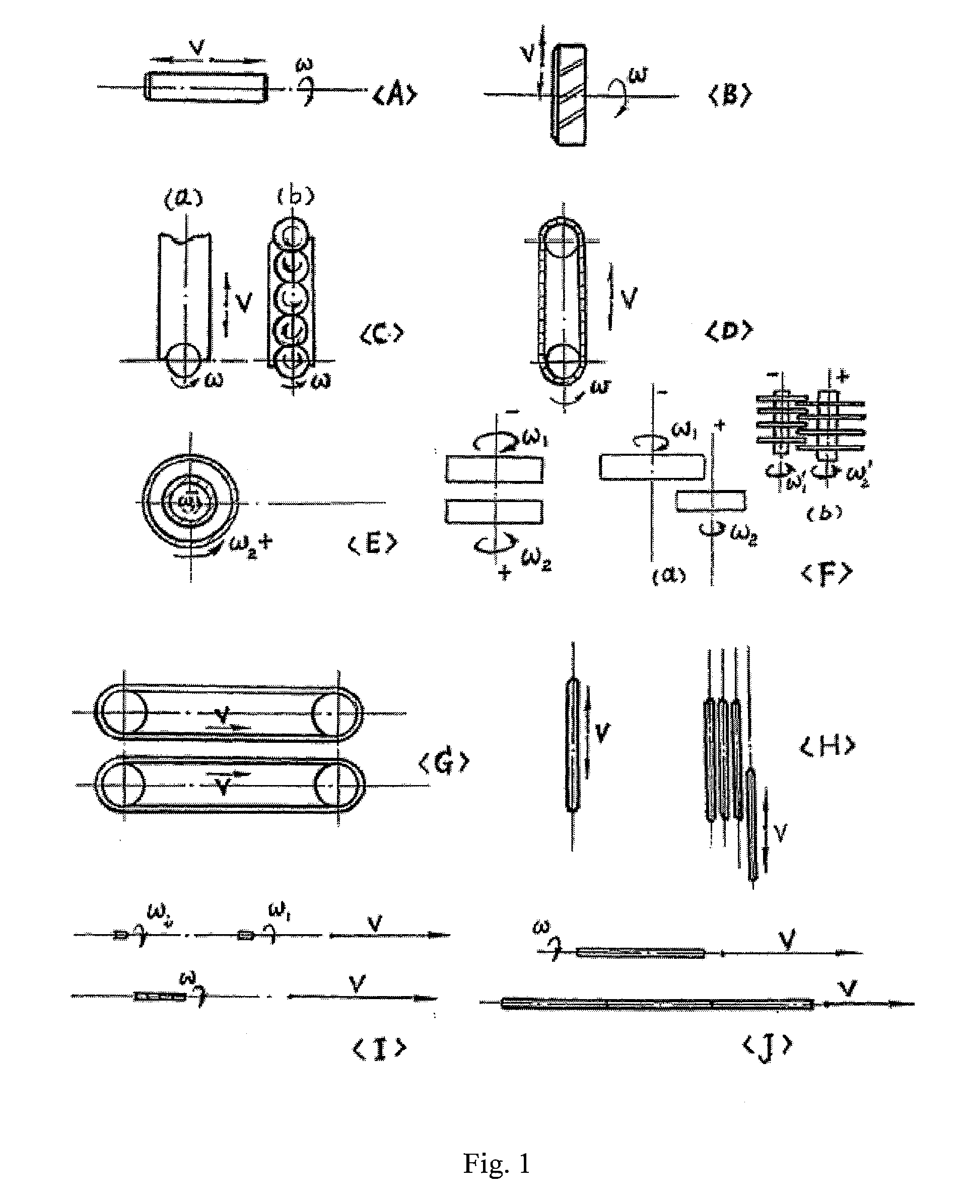
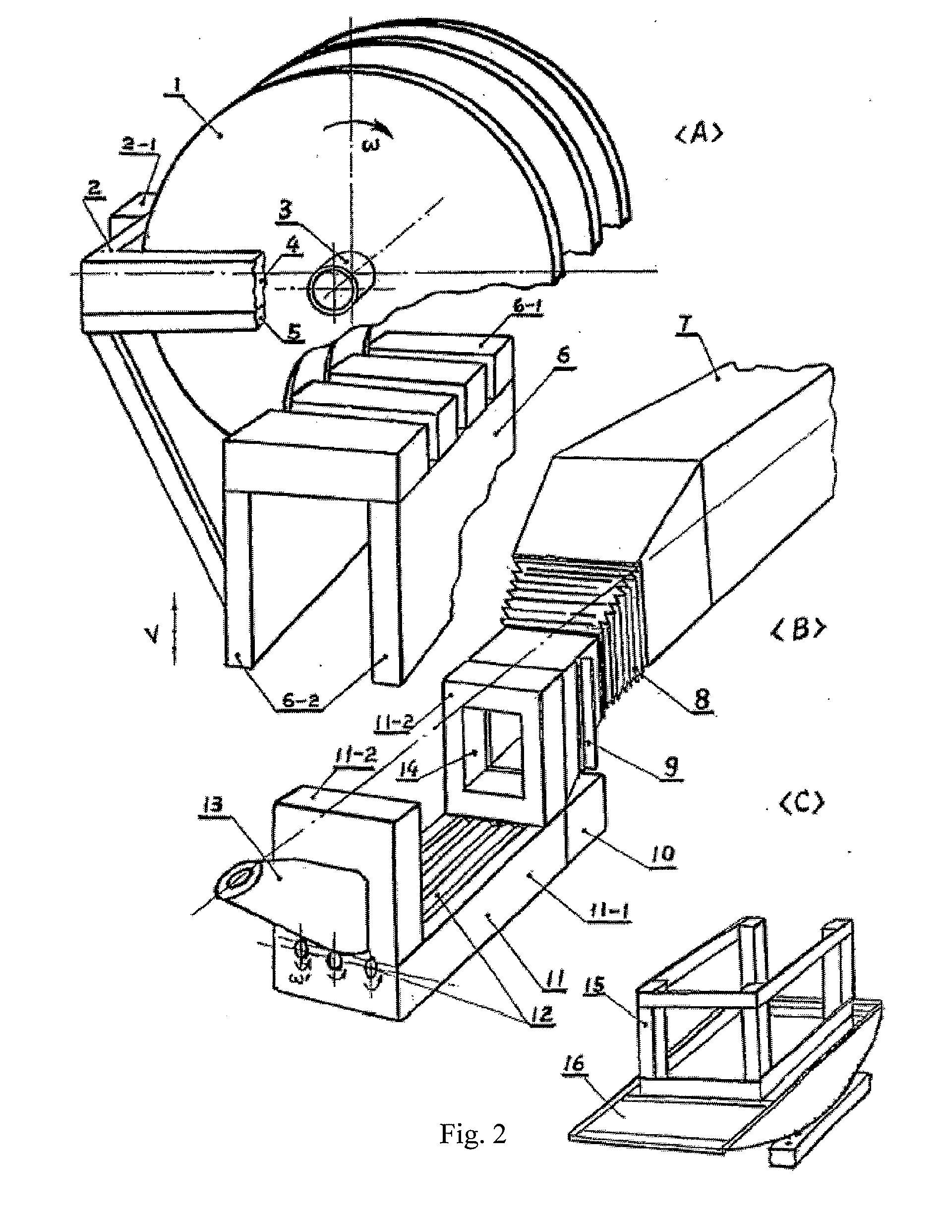
[0177]As illustrated in FIGS. 2, 3(E) and 10 for example.

[0178]FIG. 2 shows an ST dynamic arc furnace (multifunctional and versatile type). In the figure:

[0179]1. rotating-wheel dynamic electrode; 2. current-conducting arm and water inlet / outlet pipe; 2.1. power unit for furnace-roof dynamic electrode; 3. dynamic electrode rotating shaft and water inlet / outlet pipe; 4. water outlet channel; 5. water inlet channel; 6. upper furnace body; 6.1. furnace roof; 6.2. left and right furnace wall (sliding wall); 7. chimney flue (with pusher mechanism inside; small furnace can be charged through furnace door); 8. telescopic (movable) chimney flue; 9. one-way valve (for continuous melting or vacuum melting); 10. power unit for furnace-base dynamic electrode; 11. lower furnace body; 11.1. furnace base; 11.2. front and back sliding wall; 12. rotating-tube dynamic electrode; 13. tapping hole (slag-fr...

example 2

Dynamic High-Energy Beam Gun

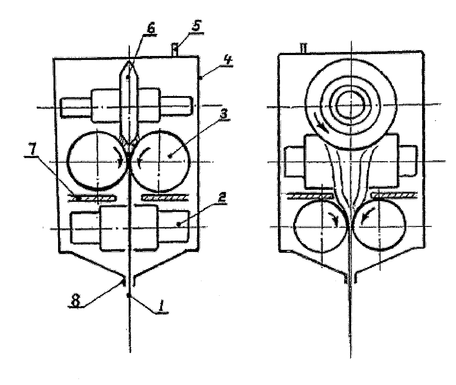
[0210]FIG. 9 shows a basic construction of an ST high-energy particle beam gun

[0211]In the figure:

[0212]1. plasma beam or electron beam (high-energy particle beam); 2. roller type focusing dynamic electrode (the 3rd stage); 3. roller type focusing dynamic electrode (the 2nd stage); 4. gun shell; 5. air inlet (or air outlet); 6. rotating wheel dynamic electrode (the 1st stage, emitting electrode); 7. insulation partition; 8. jet tip.

[0213]Design outline:

[0214]1. 2, 3 or more stages are possible;

[0215]2. Decide the voltage across stages and polarity according to requirement;

[0216]3. Preliminarily choose the type, pressure and flow rate of compressed gas according to conventional technical parameters, and after commissioning to stable, make use of the construction advantages of the gun to increase power input to the optimum value.

[0217]4. When used as electron beam gun, the voltage across stages, the vacuum degree and the compile of operating procedures can ...

example 3

Dynamic Continuous Coating (CPC)

[0219]As shown in FIGS. 4 and 5 for example.

[0220]Including dynamic electrode, dynamic crystallizer and dynamic combined intensification

[0221]FIG. 4 shows a working principle schematic of an ST-CPC one-step melt coating roller

[0222]In the figure:

[0223]1. roller; 2. ST dynamic-electrode three-phase arc furnace; 3. slag pool; 4. rotating wheel dynamic electrode; 5. molten pool; 6. crystallizer; 7. roller wheel (for intensification by rolling); 8. melt coating layer; 9. rotating tube dynamic electrode; 10. water inlet chamber ring; 11. water outlet chamber ring

[0224]Design outline:

[0225]1. Both sealing and insulation can be made by “air pressure method” (making use of the balance between air pressure and resistance) if necessary; range can be determined by resistance test made on insulation layer and rotating electrode to establish a self feedback self-adapting equilibrium system.

[0226]2. The dynamic electrode driving force can be motor force (electromag...


PUM


Abstract

A technique for the application extension of dynamic technology includes modifying a prior art static technology into a corresponding dynamic technology, and relates to a method for dynamically improving the material quality, construction and parameter of a technological equipment. The material quality, construction, parameter, and pertinent working and manufacturing process of the weak link in prior art are modified by applying a selective combination of dynamic technology, hereby to improve the quality, function, performance, accuracy, purity, high temperature, high pressure, high energy stream density etc. Typical application of the said selective combination includes dynamic electrode, dynamic spraying gun, dynamic industrial furnace, dynamic material production, dynamic high energy battery, dynamic strong electric light source, dynamic laser and dynamic nuclear reactor.

Description

TECHNICAL FIELD[0001]This invention pertains to a technique for the application extension of dynamic technology, relates to a method for modifying a prior art static technology into a corresponding dynamic technology or a method for modifying a prior art dynamic technology into a corresponding improved dynamic technology, and in particular relates to a method for dynamically improving the material quality, construction and parameter of a technological equipment.BACKGROUND ART[0002]Generally all technologies involve two major parts including process and equipment, or software and hardware. During the initial stage of technology development, most are relatively static, namely, between each component of each process and the parameter thereof, between the overall equipment status and each component of an equipment, it is generally relatively static: that is, for prior art dynamic links (power, transmission, actuating mechanism), generally only fixed and simple mechanical motion state (m...

Claims


Application Information

Patent Timeline
IPC IPC(8): F27D1/16
CPCF27B3/20H05B7/06F27D11/10
Inventor SU, XUE SONG
Owner SU XUE SONG
Learn More