Catalytic material and catalyst for purifying exhaust gas component

a catalytic material and catalyst technology, applied in physical/chemical process catalysts, metal/metal-oxide/metal-hydroxide catalysts, separation processes, etc., can solve the problems of reducing engine power and fuel economy, nox absorbing/reducing catalyst, deteriorating catalytic performance, etc., to achieve high specific surface area, effectively purifying nox, and reliable results

Inactive Publication Date: 2008-08-28
MAZDA MOTOR CORP
View PDF18 Cites 20 Cited by
  • Summary
  • Abstract
  • Description
  • Claims
  • Application Information

AI Technical Summary

Benefits of technology

[0022]The catalytic material according to the second aspect of the present invention can more reliably achieve the same effects as those of the catalytic material according the first aspect of the present invention.
[0023]The catalytic material according to the third aspect of the present invention can more reliably achieve the same effects as those of the catalytic material according to the first aspect of the present invention.
[0024]The catalyst according to the fourth aspect of the present invention can achieve the same effects as those of the catalytic material according to the first aspect of the present invention.
[0025]In the catalyst according to the fifth aspect of the present invention, the composite oxide according to any one of the first to third aspects of the present invention and a catalytic metal are contained in a catalyst layer on a particulate filter. Thus, the catalyst can achieve the same effects as those of the catalytic material according to the first aspect of the present invention.
[0026]In the catalyst according to the sixth aspect of the present invention, the composite oxide is contained in at least the lower layer located under the upper layer facing the exhaust gas channel, and an oxide particle with a high specific surface area, platinum and a NOx trapping material are contained in each of the plurality of layers. This makes it possible to effectively purify NOx during lean exhaust gas conditions, so as to reliably obtain the above effects. The composite oxide contained in the lower layer is excellent in oxygen exchange reaction during lean exhaust gas conditions, and thereby can promote an oxidation reaction of NOx to be trapped. In addition, the composite oxide having base properties can easily incorporate NOx and effectively trap the NOx. In a process of reducing tapped NOx during rich exhaust gas conditions, an amount of oxygen to be released from the composite oxide is less than that to be released from a Ce-based composite oxide. This makes it possible to effectively purify the NOx without hindering the NOx reduction reaction.
[0027]In the catalyst according to the seventh aspect of the present invention, the rhodium and the platinum are supported by the oxide particle contained in the upper layer. Thus, in a process of de-trapping NOx trapped in the lower layer located under the upper layer, most of the NOx will pass through the upper layer. This makes it possible to promote effective reduction / conversion of the de-tapped NOx, based on the Rh capable of promoting a NOx reduction reaction, so as to further reliably obtain the above effects.

Problems solved by technology

Under engine operating conditions, trapped PM will be gradually accumulated in the DPF along with an operating time to cause an increase in exhaust back pressure, leading to problems, such as a decrease in engine power and in fuel economy.
The NOx absorbing / reducing catalyst involves a problem about deterioration in catalytic performance due to a reaction with sulfur components contained in fuel.
In this case, an extra amount of fuel is inevitably consumed by the oxidation / burning of the PM.
Further, as an amount of PM to be burned increases, an amount of carbon monoxide (CO) emission is likely to undesirably increase due to occurrence of incomplete burning of the PM.

Method used


Image

  • Catalytic material and catalyst for purifying exhaust gas component
  • Catalytic material and catalyst for purifying exhaust gas component
  • Catalytic material and catalyst for purifying exhaust gas component

Examples


Embodiment Construction

[0041]With reference to the accompanying drawings, embodiments of the present invention will now be described.

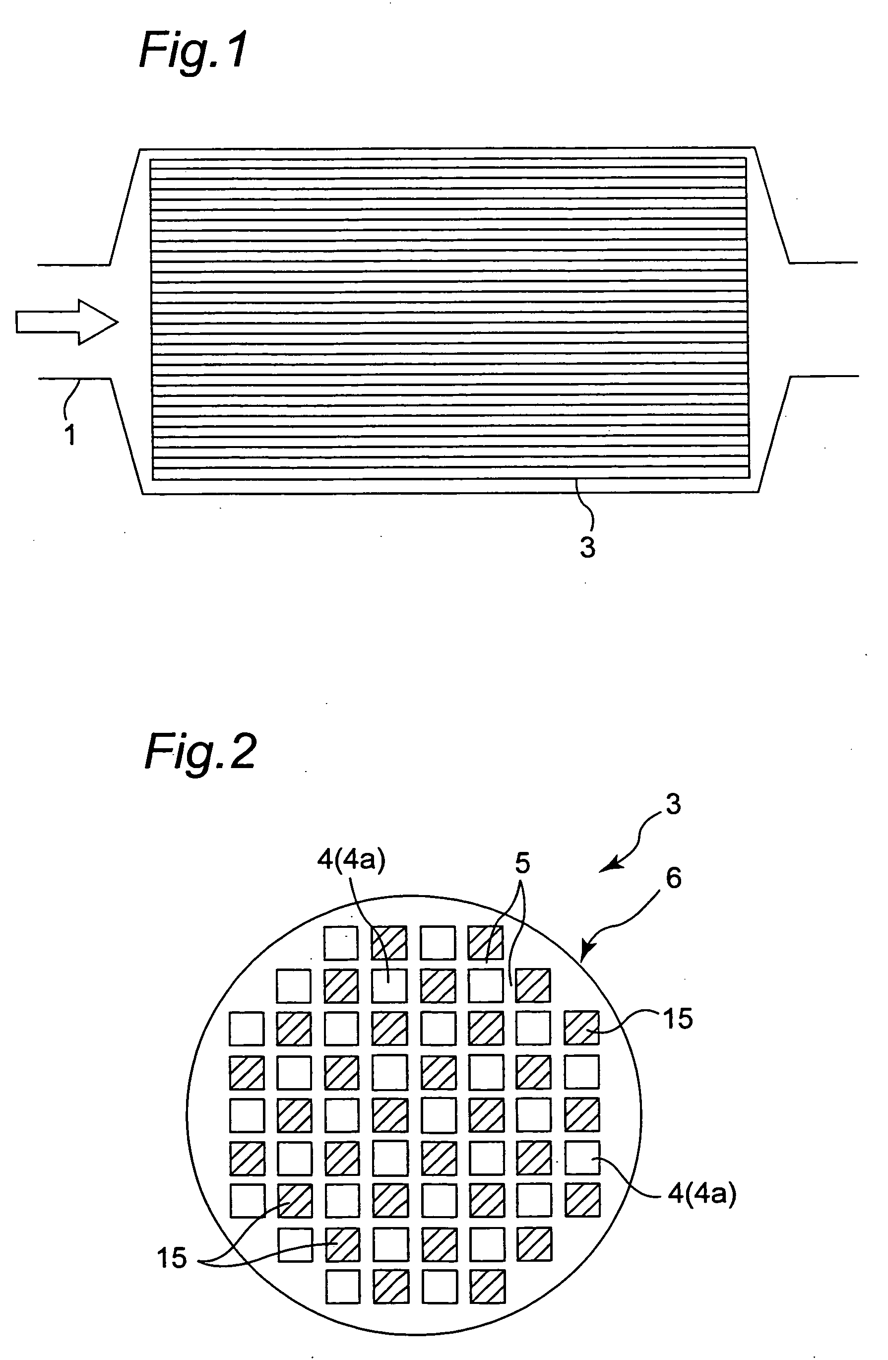
[0042]FIG. 1 shows a DPF 3 according to one embodiment of the present invention, wherein the DPF 3 is assembled to an exhaust passage 1 of a diesel engine. In FIG. 1, an exhaust pipe defining the exhaust passage 1 has an upstream end (on a right side in FIG. 1) connected to a diesel engine body (not shown) through an exhaust manifold (not shown). Exhaust gas discharged from the diesel engine body flows in a direction indicated by the arrow in FIG. 1.

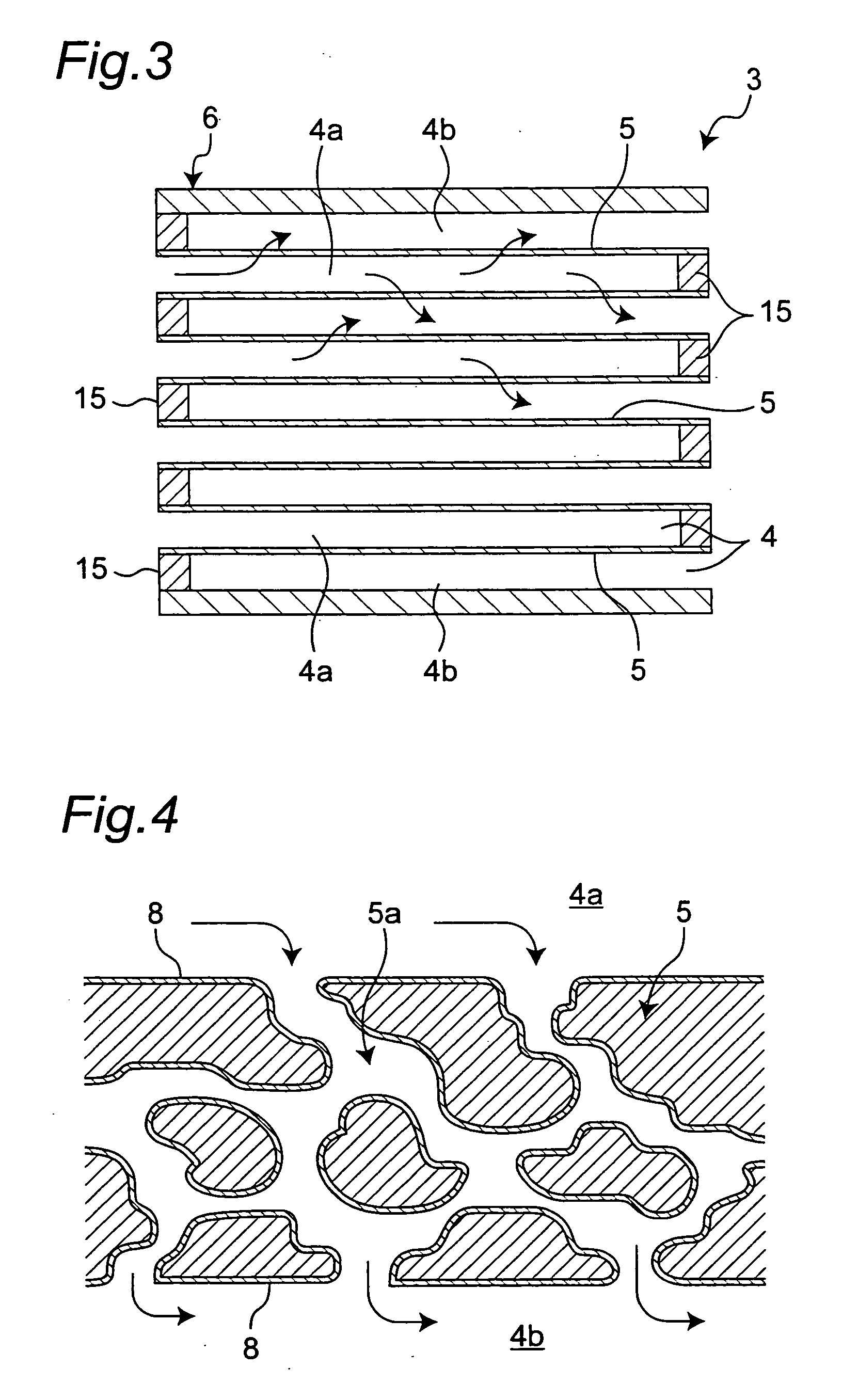
[0043]The DPF 3 is mounted in the exhaust passage to trap PM in the exhaust gas. FIGS. 2 and 3 are schematic diagrams showing the DPF 3. In this embodiment, the DPF 3 is a so-called wall-flow type filter formed to have a cylindrical outer shape. Specifically, the DPF 3 comprises a filter body 6 and a plurality of plug members 15. The filter body 6 is made of a heat-resistant ceramic material, such as cordierite, SiC or Si3N4, and...


PUM

PropertyMeasurementUnit
specific surface areaaaaaaaaaaa
temperatureaaaaaaaaaa
thicknessaaaaaaaaaa

Abstract

Disclosed is a catalytic material for purifying an exhaust gas component. The catalytic material comprises a composite oxide which contains, as essential components, zirconium (Zr) and neodymium (Nd), and further contains a rare-earth metal R other than cerium (Ce) and neodymium (Nd), wherein each of the zirconium, neodymium and rare-earth metal R constituting the composite oxide is contained, in the form of oxide, in such a manner that a ratio of Nd2O3/(ZrO2+Nd2O3+RO) is 3 mol % or more, and a ratio of (Nd2O3+RO)/(ZrO2+Nd2O3+RO) is 33 mol % or less. The catalytic material of the present invention can oxidize/burn PM in a short period of time, while suppressing CO emission during the burning of the PM, and can achieve further enhanced NOx conversion performance.

Description

RELATED APPLICATION[0001]This application is based on Japanese Patent Applications Nos. 2007-35095 and 2008-12798, the contents of which are incorporated herein by references.BACKGROUND OF THE INVENTION[0002]The present invention relates to an exhaust gas component purifying catalytic material, and an exhaust gas component purifying catalyst which comprises a catalyst support substrate having thereon a catalyst layer containing the exhaust gas component purifying catalytic material.[0003]In vehicles, such as automobiles, an exhaust gas component purifying catalyst is provided in an exhaust gas passage of an engine to purify exhaust gas discharged from the engine. Particularly, an exhaust gas component purifying catalyst for a vehicle equipped with a diesel engine or a lean-burn gasoline engine is required to have a function of minimizing unburned carbon particulates (so-called “particulate matter (PM)”) and nitrogen oxides (NOx) contained in exhaust gas.[0004]For instance, on concer...

Claims


Application Information

Patent Timeline
Patent Type & Authority Applications(United States)
IPC IPC(8): B01J23/92B01J23/10B01D53/34
CPCB01D53/945Y02T10/22B01D2255/1025B01D2255/2042B01D2255/206B01D2255/20715B01D2255/9022B01D2255/91B01J23/002B01J23/10B01J23/63B01J35/002B01J35/10B01J37/0242B01J37/0244B01J37/0248B01J37/03B01J2523/00C01G25/00C01G25/006C01P2002/50C01P2002/72C01P2006/12C01P2006/13F01N3/0821F01N3/0842F01N2510/06F01N2510/0684B01D2255/1021B01J2523/3706B01J2523/3725B01J2523/48B01J2523/3737B01J2523/3718B01J2523/35B01J2523/3787B01J2523/36Y02T10/12
Inventor SUZUKI, KENJIHARADA, KOICHIROYAMADA, HIROSHIOKAMOTO, KENJITAKAMI, AKIHIDE
Owner MAZDA MOTOR CORP
Why Eureka
Try Eureka