Eureka AIR delivers breakthrough ideas for toughest innovation challenges, trusted by R&D personnel around the world.

Dual injection type internal combustion engine

a technology of internal combustion engine and injection type, which is applied in the direction of machines/engines, electric control, instruments, etc., can solve the problems of increasing the background noise level, the value of the background noise level set in a prescribed operating range of the engine is not always a suitable value in another operating range of the engine, and the background noise level would increase, etc., to achieve accurate background learning

Inactive Publication Date: 2008-08-28
TOYOTA JIDOSHA KK
View PDF3 Cites 4 Cited by
  • Summary
  • Abstract
  • Description
  • Claims
  • Application Information

AI Technical Summary

Benefits of technology

[0014]The present invention was made in view of the foregoing, and its object is to suppress knocking during background learning and to provide a dual injection type internal combustion engine that allows execution of accurate background learning.

Problems solved by technology

Generally, the higher the engine speed and the higher the engine load, the higher becomes the background noise level.
As the background noise level varies in accordance with the operating state of the engine, the value of the background noise level set in a prescribed operating range of the engine is not always a suitable value in another operating range of the engine.
By way of example, when a threshold value is set using a low background noise level as a reference in a low speed range of the engine and the engine enters a high speed operating state, the background noise level would increase and the sensor output value exceeds the threshold value because of the background noise itself, resulting in an erroneous determination that knock is occurring.
When background learning is being executed, however, the output signals from the knock sensor are treated exclusively as the background noise while the threshold value for knock determination is not yet determined, and therefore, knock determination is impossible.
Accordingly, it is also impossible to perform knock control for adjusting the spark timing and the like in accordance with the knock determination results and hence, knocking may possibly occur.

Method used


Image

  • Dual injection type internal combustion engine
  • Dual injection type internal combustion engine
  • Dual injection type internal combustion engine

Examples


Embodiment Construction

[0038]In the following, embodiments of the present invention will be described with reference to the figures.

[0039](1) Basic Configuration

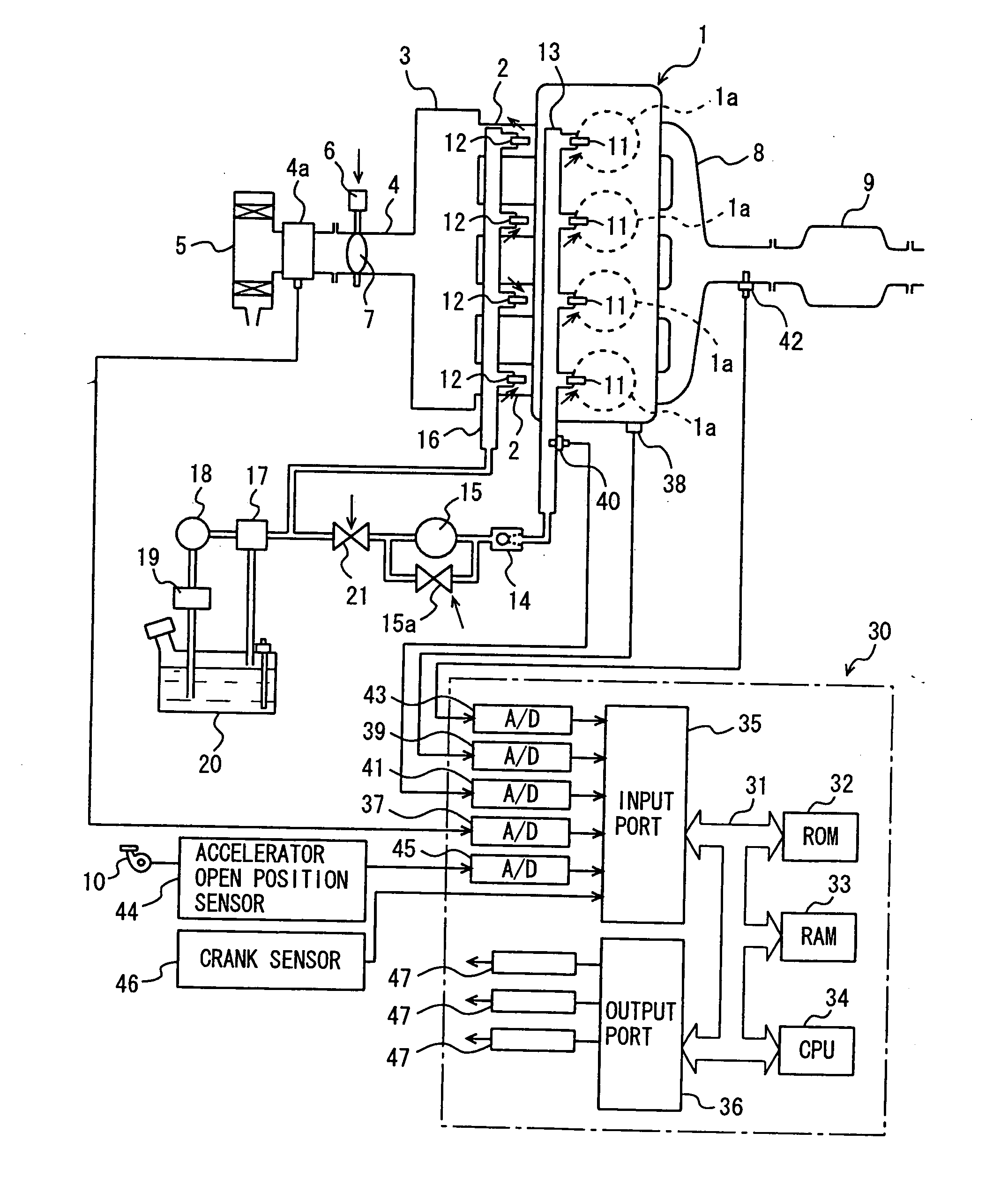
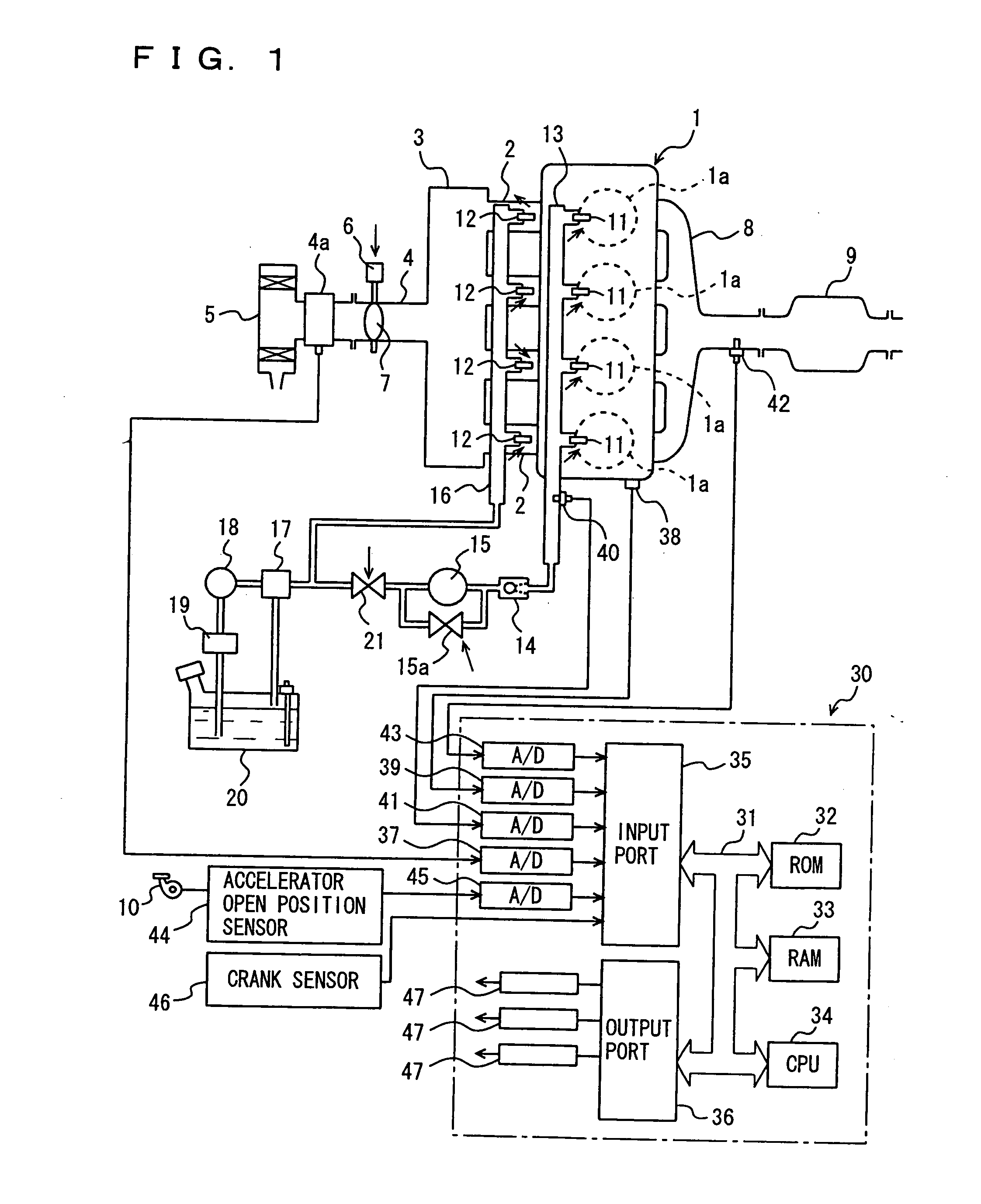
[0040]First, referring to FIG. 1 showing the schematic configuration of the dual injection type internal combustion engine in accordance with the present invention, an engine 1 includes a plurality of (four in the present embodiment) cylinders 1a, and each cylinder 1a is connected through a corresponding intake branch pipe 2 to a common surge tank 3. Surge tank 3 is connected through an intake duct 4 to an air cleaner 5, and in intake duct 4, an air flow meter 4a, and a throttle valve 7 driven by an electric motor 6 are arranged. Throttle valve 7 has its opening position controlled based on an output signal of an electronic control unit 30, independent from an accelerator pedal 10. Each cylinder 1a is coupled to a common exhaust manifold 8, which manifold 8 is coupled to a three-way catalyst converter 9.

[0041]For each cylinder 1a, an intake port, ...


PUM


Abstract

A dual injection type internal combustion engine including an injector for in-cylinder injection and an injector for intake manifold injection includes a learning device for learning a background noise level based on an output signal of a knock sensor, and a knocking suppression control device for performing, while learning the background noise level, knocking suppression control by controlling fuel injection of the injector for in-cylinder injection or the injector for intake manifold injection. Alternatively, the engine includes a fixing device for fixing, while learning the background noise level, a start timing or end timing of fuel injection by the injector for in-cylinder injection at a basic timing determined by an operating state of the engine.

Description

[0001]This application is a division of U.S. patent application Ser. No. 11 / 304,539, filed Dec. 16, 2005, the entire contents of which are hereby incorporated by reference.[0002]This nonprovisional application is based on Japanese Patent Application No. 2005-000187 filed with the Japan Patent Office on Jan. 4, 2005, the entire contents of which are hereby incorporated by reference.BACKGROUND OF THE INVENTION[0003]1. Field of the Invention[0004]The present invention relates to a dual injection type internal combustion engine and, more specifically, to a dual injection type internal combustion engine including an injector for in-cylinder injection for injecting fuel to the inside of a cylinder and an injector for intake manifold injection for injecting fuel to the intake manifold or to an intake port, provided with learning means for learning background noise level used as a reference at the time of knock determination.[0005]2. Description of the Background Art[0006]A so-called dual i...

Claims


Application Information

Patent Timeline
Patent Type & Authority Applications(United States)
IPC IPC(8): F02D45/00F02D13/02F02D41/04F02D41/34F02M63/00F02P5/152F02P5/153
CPCG01L23/225Y02T10/44F02D41/401F02D35/027F02D41/3094F02D35/02Y02T10/40
Inventor MIYASHITA, SHIGEKI
Owner TOYOTA JIDOSHA KK
Why Eureka
Eureka Blog
Learn More