
Natural gas engine structure for mixed double-injection of cylinder outer cold water and in-cylinder hot water

A natural gas and external cold water technology, applied in the direction of internal combustion piston engine, gaseous engine fuel, engine components, etc., can solve the problems of knocking nitrogen oxides, limiting the thermal efficiency of internal combustion engines, and increasing power, and achieves suppression of knocking and super knocking, The effect of improving fuel economy and emission characteristics, good application prospects

Inactive Publication Date: 2018-05-18
TONGJI UNIV
View PDF6 Cites 4 Cited by
  • Summary
  • Abstract
  • Description
  • Claims
  • Application Information

AI Technical Summary

Problems solved by technology

However, there are technical bottlenecks in existing natural gas engines, which are prone to knocking and a certain amount of nitrogen oxides, and the exhaust gas discharged from the cylinder takes about one-third of the heat of the cylinder, which limits the further improvement of the thermal efficiency and power per liter of the internal combustion engine.

Method used


Image

  • Natural gas engine structure for mixed double-injection of cylinder outer cold water and in-cylinder hot water

Examples


Embodiment 1

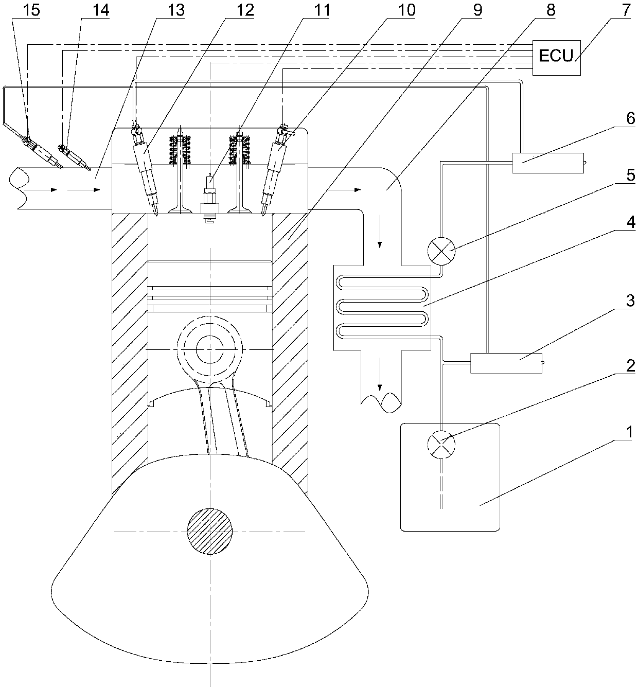
[0033] Such as figure 1 As shown, a natural gas engine structure with cold water outside the cylinder and hot water in the cylinder mixed with double injection, the structure includes a natural gas engine body 9, an intake manifold 13 and an exhaust manifold 8 arranged on the natural gas engine body 9, a natural gas injection device, a spark plug 11 arranged in the natural gas engine body 9, an in-cylinder sprinkler 12 arranged in the natural gas engine body 9, a high-pressure water pump unit communicated with the in-cylinder sprinkler 12, arranged in the intake manifold 13 The water sprayer 15 outside the cylinder, the low-pressure water pump unit connected with the water sprayer 15 outside the cylinder, the heat exchanger 4 arranged between the low-pressure water pump unit and the high-pressure water pump unit, respectively connected with the natural gas injector, the spark plug 11, the in-cylinder The electronic controller 7 electrically connected to the water sprayer 12, t...

Embodiment 2

[0041] In this embodiment, the natural gas injector is an in-cylinder natural gas injector 10 arranged in the body 9 of the natural gas engine. All the other are with embodiment 1.

Embodiment 3

[0043] In this embodiment, the natural gas injector is an out-of-cylinder natural gas injector 14 arranged on the intake manifold 13 .

[0044] All the other are with embodiment 1.


PUM


Abstract

The invention relates to a natural gas engine structure for mixed double-injection of cylinder outer cold water and in-cylinder hot water. The natural gas engine structure comprises a natural gas engine body, an air inlet manifold, an exhaust manifold, a natural gas injector, a spark plug, an in-cylinder water sprayer, a high-pressure water pump unit, a cylinder outer water sprayer, a low-pressurewater pump unit, a heat exchanger and a electronic controller; and the in-cylinder water sprayer is arranged in the natural gas engine body, the high-pressure water pump unit communicates with the in-cylinder water sprayer, the cylinder outer water sprayer is arranged in the air inlet manifold, the low-pressure water pump unit communicates with the cylinder outer water sprayer and the electroniccontroller is electrically connected with the natural gas injector, the spark plug, the in-cylinder water sprayer, the high-pressure water pump unit, the cylinder outer water sprayer and the low-pressure water pump unit. Compared with the prior art, the natural gas engine structure has the advantages that hot water sprayed in a cylinder is used for rapidly vaporizing to absorb heat, so that the temperature in the part, close to a combustion top dead center, of the cylinder is reduced, and the generation of knocking is inhibited; meanwhile, the heat for heating the water comes from recovering tail gas energy by a exchanger, so that the working medium in the combustion process is increased, the heat loss is reduced, and the heat efficiency of the natural gas engine is improved.

Description

technical field [0001] The invention belongs to the technical field of internal combustion engines, and relates to a natural gas engine structure with cold water outside the cylinder and hot water in the cylinder mixed with double injection. Background technique [0002] Natural gas is the clean energy with the largest reserves in the world. It has the advantages of rich resources, low emission pollution, and low price. It is considered to be a very promising fuel. energy. In recent years, with the development and maturity of hydraulic fracturing technology and horizontal drilling technology, the recoverable natural gas reserves have grown rapidly, which will have an important impact on my country's energy development pattern. CO produced by combustion 2 And PM is very little, so it is also called "clean fuel". [0003] For spark-ignited natural gas engines, the mixed gas in the traditional lean-burn mode cylinder releases a large amount of heat during combustion, which i...

Claims


Application Information

Patent Timeline
Patent Type & Authority Applications(China)
IPC IPC(8): F02M25/022F02M25/028F02M25/03F02B43/10
CPCF02B43/10F02B2043/103F02M25/0221F02M25/0227F02M25/028F02M25/03Y02T10/30
Inventor 邓俊吴志军吴静涛康哲胡宗杰李理光
Owner TONGJI UNIV
Learn More