Method of operating an adsorption refrigeration system

a refrigeration system and refrigeration system technology, applied in sustainable buildings, energy-efficient heating/cooling, lighting and heating apparatus, etc., to achieve the effect of dampening any temperature instability within the system, improving the temperature stability, and poor thermal conductivity of the coolant gas

Active Publication Date: 2008-09-04
OXFORD INSTR NANOTECH TOOLS
View PDF3 Cites 7 Cited by
  • Summary
  • Abstract
  • Description
  • Claims
  • Application Information

AI Technical Summary

Benefits of technology

[0038]The system may further comprise the use of heat pipes such that the primary chamber may be coupled thermally to a heat pipe, the heat pipe comprising a sealed heat pipe chamber containing a coolant and having an upper region and a lower region in fluid communication with one another, such that when the system is in use, the primary chamber cools the upper region of the heat pipe with respect to the lower region whereby the coolant is condensed into coolant liquid and moves under gravity to the lower region. With regard to the heat pipe, the terms “upper” and “lower” relate to the operational position of the heat pipe with respect to a downward gravitational direction. A plurality of such heat pipes may be provided. Heat pipes are beneficial in that they improve the temperatur

Problems solved by technology

One problem with using such systems is that they are effectively “single-shot”, meaning that they may on

Method used


Image

  • Method of operating an adsorption refrigeration system
  • Method of operating an adsorption refrigeration system
  • Method of operating an adsorption refrigeration system

Examples


Embodiment Construction

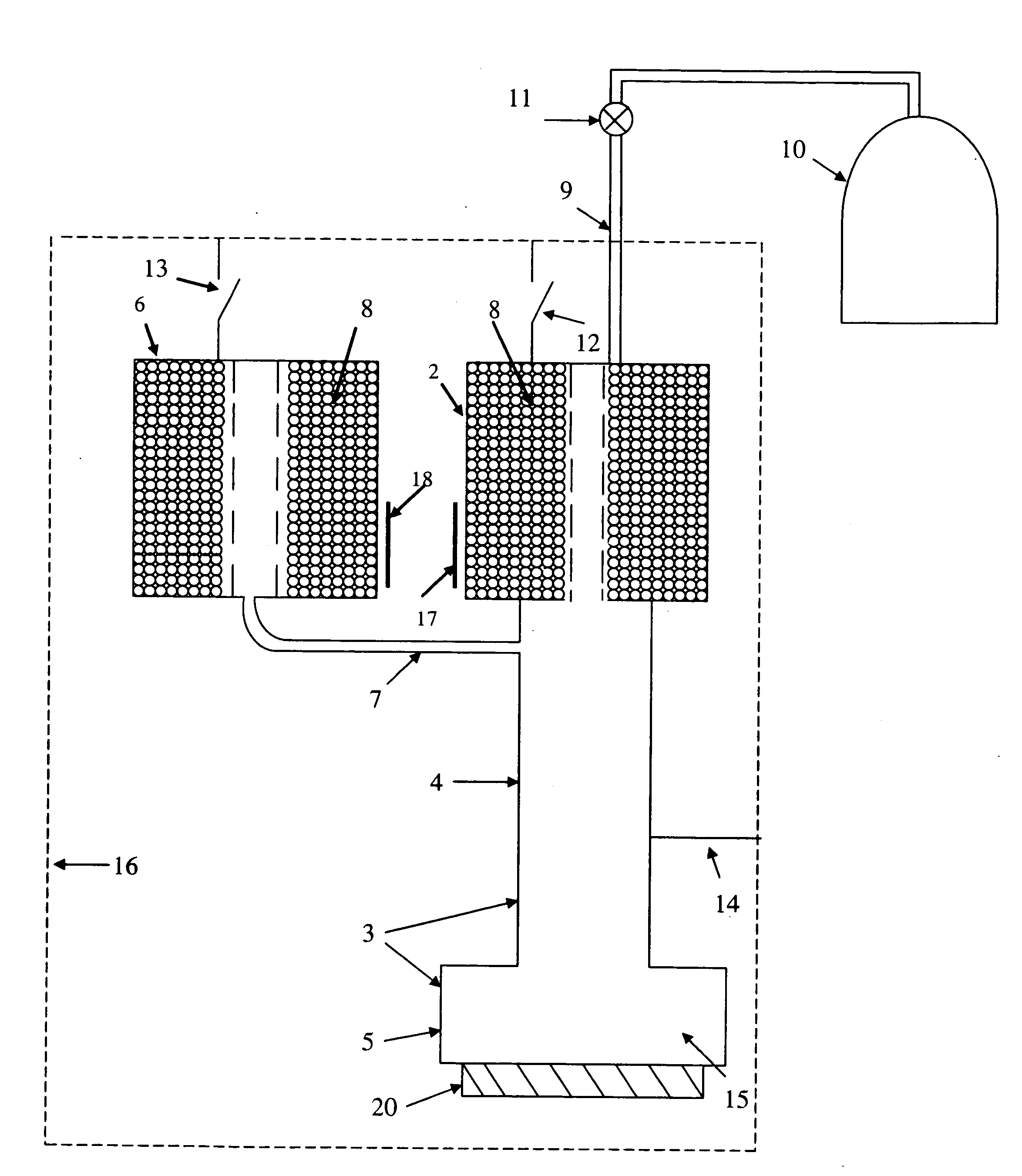
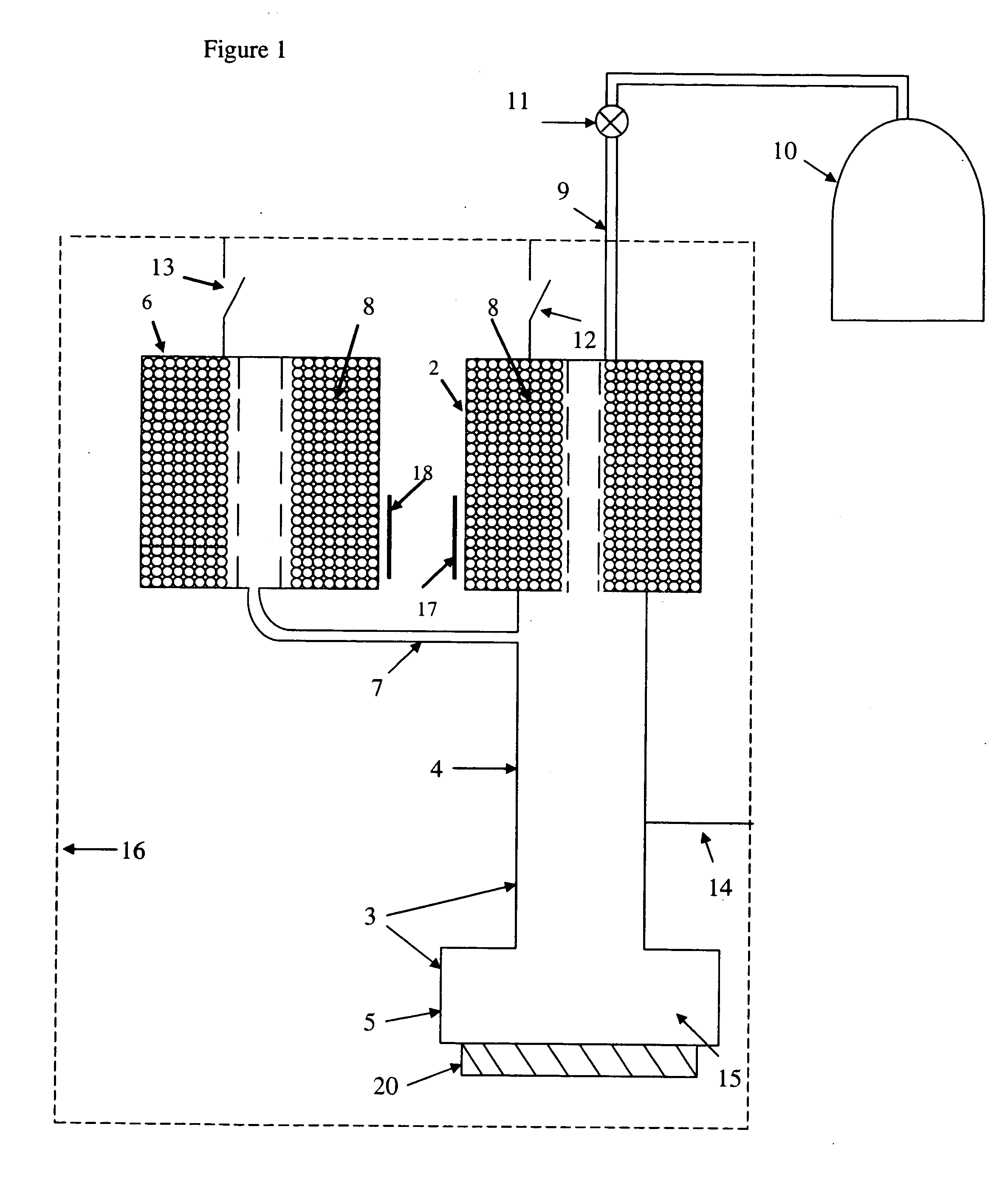
[0053]FIG. 1 shows a schematic representation of a first example system which is generally indicated at 1. A primary adsorption pump 2 is connected to a primary chamber 3, the primary chamber comprising a primary pumping line 4 and a primary pot 5. As can be seen, the primary pumping line is effectively a large diameter tube (typical dimensions being a diameter of about 8 millimetres and a length of about 200 millimetres or less). At an upper end of the primary pumping line 4 is positioned the primary adsorption pump 2, and at a lower end is located the primary pot 5. This means that any gas within the pot 5 is in fluid communication with the interior of the primary adsorption pump 2. A secondary adsorption pump 6 is provided, this being placed in fluid communication with the interior of the pumping line 4 by virtue of a high fluid impedance conduit 7 in the form of a stainless steel capillary. This has a diameter of about 1 millimetre and a length of about 200 millimetres or less. ...


PUM

PropertyMeasurementUnit
Temperatureaaaaaaaaaa
Pressureaaaaaaaaaa

Abstract

A method is provided of operating an adsorption refrigeration system. The system comprises a primary adsorption pump which is arranged in communication with a primary chamber containing coolant, a secondary adsorption pump and a high fluid impedance conduit which places the secondary adsorption pump and primary chamber into communication. The method comprises saturating the primary and secondary adsorption pumps with coolant whilst each pump is at its respective operational temperature. The pumps are then heated above their operational temperatures to desorb the coolant such that the coolant pressure in the primary chamber and the secondary adsorption pump substantially equalises through the conduit whilst the primary chamber is cooled. The secondary adsorption pump is then cooled causing coolant gas to be adsorbed and therefore a reduction in temperature and pressure of the coolant in the primary chamber is effected. The primary adsorption pump is then cooled to an operational temperature causing adsorption of the coolant and therefore a reduction in temperature and pressure of the coolant in the primary chamber.

Description

FIELD OF INVENTION[0001]The present invention relates to a method of operating an adsorption refrigeration system, together with a system suitable for performing the method.BACKGROUND TO THE INVENTION[0002]Adsorption refrigeration systems are well known in the field of refrigeration and particularly cryogenics, for providing very low temperatures in a region such as a chamber. Adsorption refrigeration systems operate by the provision of an amount of liquid coolant within a chamber to be cooled. This is placed in gaseous communication with an amount of adsorbing material such as charcoal, the entire system being closed such that the amount of coolant within the system remains constant. Typically the coolant in liquid form is obtained by condensation of gaseous coolant in contact with the cold walls of a member pre-cooled by an external source. This is performed in many conventional adsorption refrigeration systems by the use of a “1K pot”.[0003]A second and alternative method of obta...

Claims


Application Information

Patent Timeline
IPC IPC(8): B01D8/00F25B17/08
CPCF25B17/00Y02B30/64F25B2500/13F25B17/08Y02B30/00Y02A30/27F25B17/083F25B25/005
Inventor MIKHEEV, VLADIMIR
Owner OXFORD INSTR NANOTECH TOOLS
Why Eureka
Try Eureka