Forming Tool

Inactive Publication Date: 2008-09-04
ENGINEERED PRODS SWITZERLAND
View PDF9 Cites 14 Cited by
  • Summary
  • Abstract
  • Description
  • Claims
  • Application Information

AI Technical Summary

Benefits of technology

[0046]A particular advantage of the invention is that the structured surface of the metallic glass layer can be provided with a very fine deterministic structure. It is a preferred embodiment of the invention that the structured surface be deterministic and a more preferred embodiment that the deterministic structured surface contain features which are sub-micron in size.
[0047]A second aspect of the invention is a method of modifying the surface of a work-piece wherein at least one surface of the work-piece comes into contact with the structured surface of a forming tool at least once, characterised in that the forming tool is comprised of a substrate and a metallic glass layer on at least the working surface of the forming tool and the metallic glass layer possesses a structured surface whereby the structured surface of the metallic glass layer reproduces in the surface of the work-piece.
[0048]The nature of the metallic glass layer in terms of its composition and thickness are typically the same as those described above in connection with the forming tool. Like

Problems solved by technology

In the case of multiple pass embossing, deterministic structures can lead to interference effects whilst stochastic structures generally will not.
In work rolls used in the above mentioned polymer processing, a deterministic structure could be imparted into the surface of the work roll by a machining operation, but this would be expensive and such work rolls have a limited life whereafter they need to be refurbished or re-machined, operations which can be expensive and time consuming.
Furthermore, the quality of indentation of the deterministic structure into the surface of the work-piece can deteriorate over time due to wear of the forming surface of the forming tool leading to variable quality in the

Method used


Image

  • Forming Tool
  • Forming Tool
  • Forming Tool

Examples


Embodiment Construction

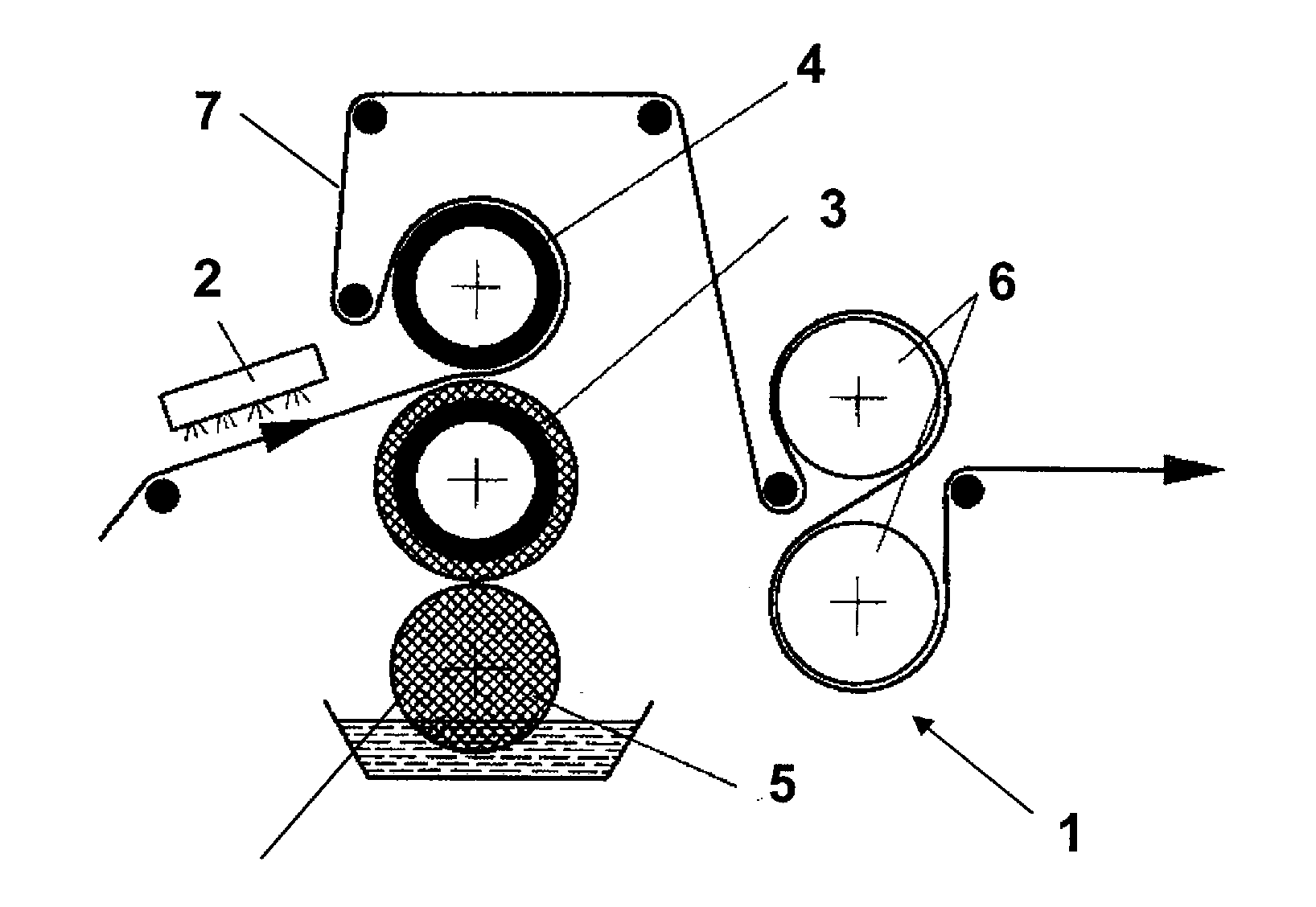
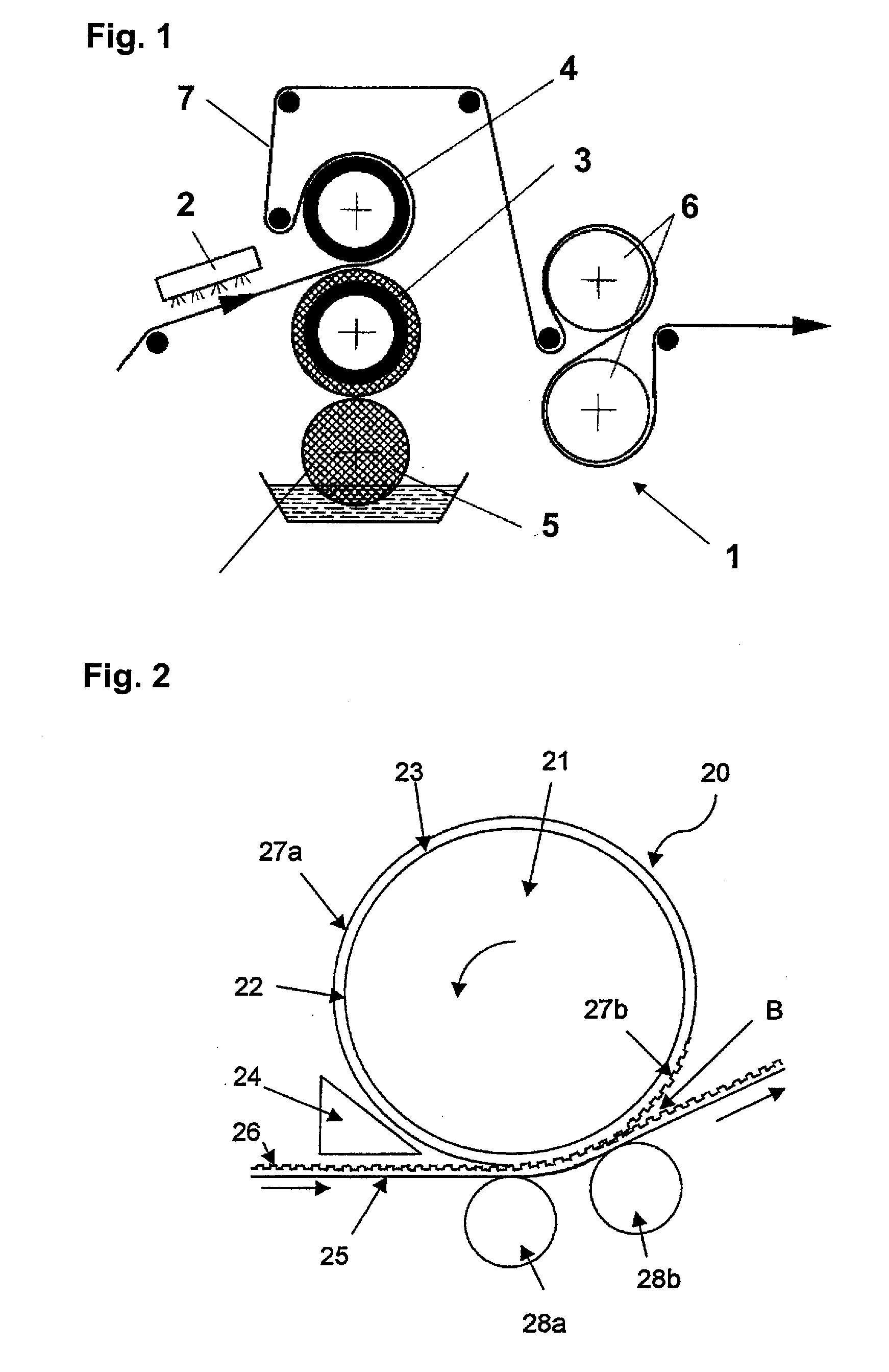
[0066]In FIG. 1 the embossing calender 1 contains an infrared heater 2 to soften the continuous sheet material 7 or at least its surface. The sheet material 7 can be a plastic sheet, or a sheet made of one or more materials other than plastic, coated with a plastic material, in particularly a thermoplastic material. Sheet material can comprise e.g. a metal, reinforcing fibres or fibre fabrics. The softened or melted plastic surface of the sheet material is then embossed by means of a chilled embossing roll 4 coated with metallic glass, which interacts with a second roll 3 producing a counter-pressure to the sheet material 7 passing the roll gap. The calender unit 1 further comprises a cooling roll 5 to cool the counter-pressure roll 3 and cooling rolls 6 to cool the sheet material.

[0067]In FIG. 2 the forming tool 20 is in the form of a cylindrical work roll of a polymer processing unit as e.g. described under FIG. 1. The forming tool 20 comprises a cylindrical substrate 21 and a met...


PUM

PropertyMeasurementUnit
Thicknessaaaaaaaaaa
Thicknessaaaaaaaaaa
Thicknessaaaaaaaaaa

Abstract

A forming tool (20) it comprises a substrate (21) and a metallic glass layer (23) on at least the working surface (22) of the forming tool (20) wherein the forming tool is one of:
    • a) a forming tool of an extrusion press;
    • b) a die of a wire-drawing machine;
    • c) a roll of a polymer processing unit.

Description

BACKGROUND OF THE INVENTION[0001]The present invention relates to a forming tool, a method of modifying the surface of a work-piece or a ductile compound wherein at least one surface of the work-piece or the ductile compound comes into contact with the surface of a forming tool at least once and a method of structuring the outer surface of a forming tool.[0002]In the materials processing industries there are many types of forming operation. In the metals industry forming operations can include, for example:[0003]an extrusion process which is defined as the process of shaping material, such as aluminium, by forcing it to flow through a shaped opening in a die. Extruded material emerges as an elongated piece with the same profile as the die opening.[0004]a wire drawing process, which is a metal-reducing process in which a wire rod is pulled or drawn through a single die or a series of continuous dies, thereby reducing its diameter. Because the volume of the wire remains the same, the ...

Claims


Application Information

Patent Timeline
IPC IPC(8): B21D37/00
CPCB21C3/00B21C3/02B21C3/16B21C3/18B21C25/025B21C25/04F16D3/74B21K5/20B23P15/24B29C33/424B29C33/56C22C45/00B21J1/006
Inventor DENEUVILLE, PATRICK
Owner ENGINEERED PRODS SWITZERLAND
Why Eureka
Try Eureka