Ultrasonic Assembly Method

a technology of ultrasonic assembly and assembly method, which is applied in the direction of lamination, domestic objects, applications, etc., can solve the problems of high cost, incompatibility with automation, and inability to achieve true uniform welding joints, and achieve the effect of convenient us

Inactive Publication Date: 2008-09-04
EURON AERONAUTIC DEFENCE & SPACE
View PDF4 Cites 17 Cited by
  • Summary
  • Abstract
  • Description
  • Claims
  • Application Information

AI Technical Summary

Benefits of technology

[0015]One objective of the invention is to propose an assembly method with reduced costs that may be easily automated.
[0018]Another objective of the invention is to propose an assembly method that provides a welded joint with a satisfactory mechanical resistance without the need for a metallic reinforcement so as to avoid any problems of electromagnetic incompatibility and damage caused by lightning.
[0023]It is advantageous to improve the quality of the joint to maintain a pressure on the two parts in the interface zone in front and / or behind the region positioned opposite the ultrasonic source. The notions of in front or behind are in relation to the direction of displacement of the ultrasonic source.
[0027]The displacement may be made in one, two or three dimensions, which permits the easy assembly of parts with extremely diverse and complex forms.
[0032]To improve the quality of the joint, it is preferable for the ribs to be directed in the direction of the displacement.
[0034]When several ultrasonic sources are used, it is preferable for them to have the same synchronous displacement so as to reduce the assembly time.

Problems solved by technology

Static welding permits continuous and uniform joints of good quality to be obtained but leads to high costs and is not compatible with automation as the parts to be assembled are of large dimensions.
The welded joint obtained is not truly uniform as it is formed by a series of joined points; it contains discontinuities.
Such a welded joint is not satisfactory due to its lack of homogeneity and risks causing mechanical problems.
However in this case, the welded joint is electrically conductive due to the presence of the metallic framework.
It may even be damaged if it is hit by lightning.
In all cases, the welded joint obtained is not entirely satisfactory.
The larger the base, the more ultrasonic energy needs to be provided to obtain the joint and the higher the cost of the joined point.
Overall this method is costly in terms of cycle and energy.
This method is made complex by the fact that the carbon loading the thermoplastic material is made electrically conductive.
The same disadvantages as with ultrasonic welding with a metallic framework appear.
If the load in carbon exceeds approximately 5% in volume, they become absorbent and this method may not be used.

Method used


Image

  • Ultrasonic Assembly Method
  • Ultrasonic Assembly Method
  • Ultrasonic Assembly Method

Examples


Embodiment Construction

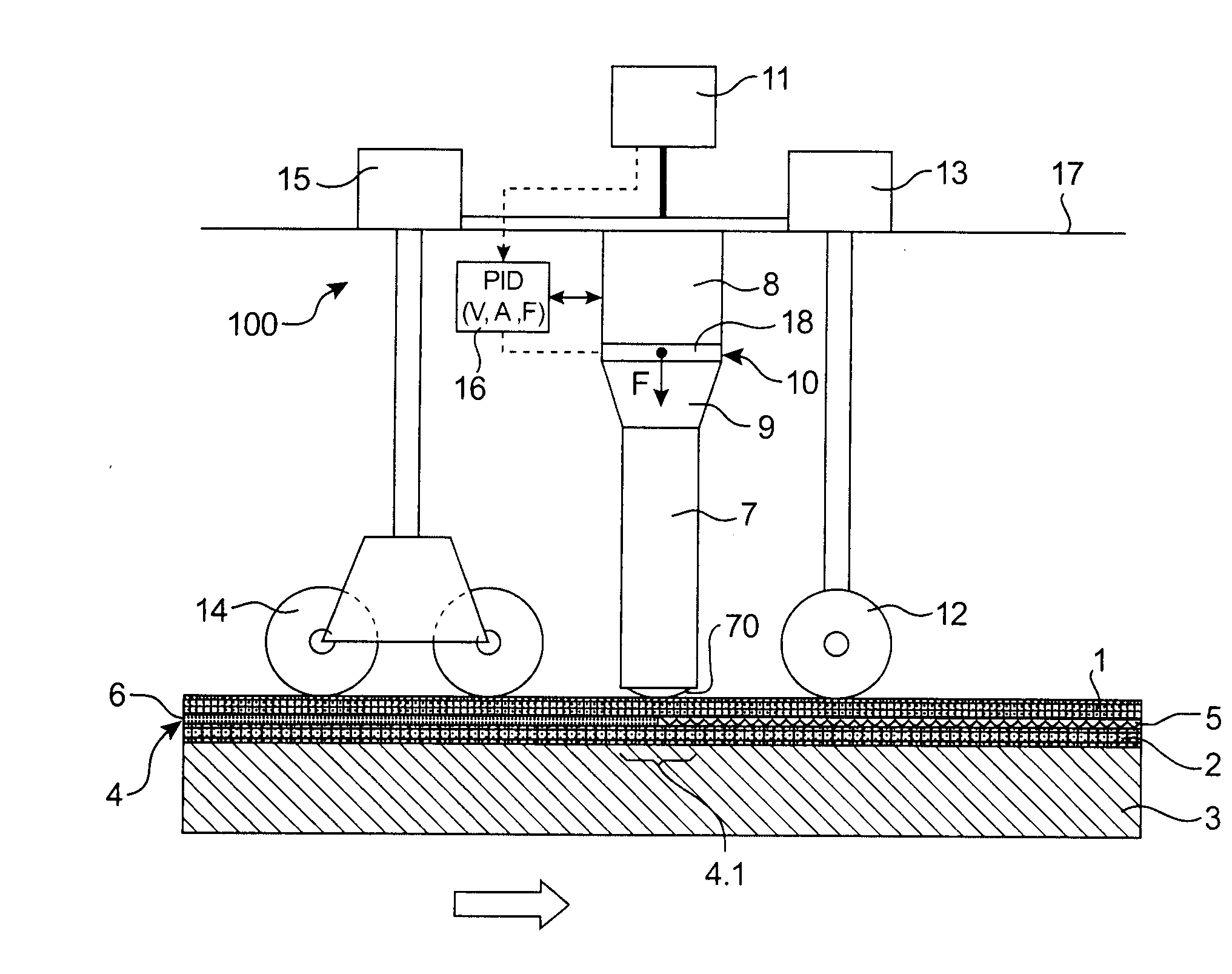
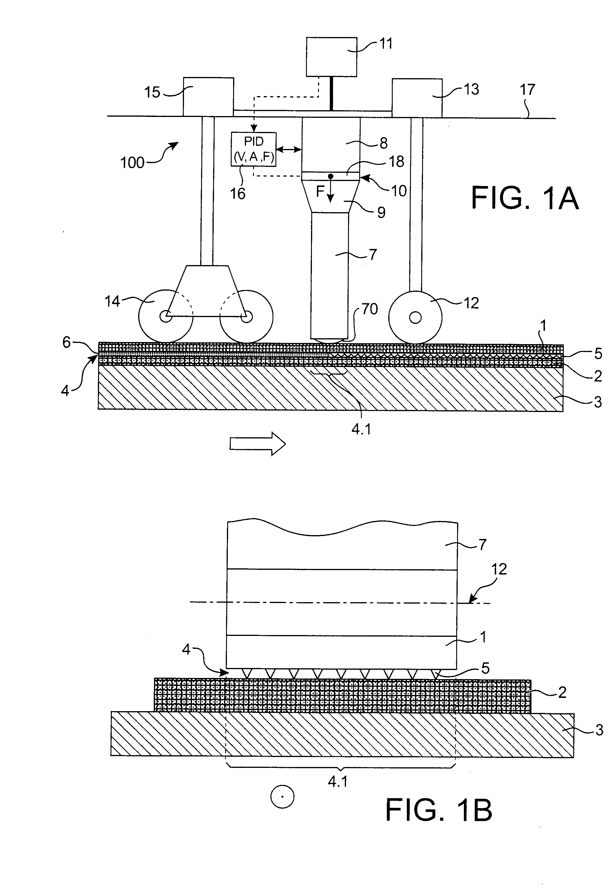
[0013]This invention has as its objective to propose an assembly method for at least two thermoplastic resin based rigid parts that does not have the limitations and difficulties mentioned above.

[0014]One objective in particular is to propose an assembly method providing the most uniform and continuous welded joint possible.

[0015]One objective of the invention is to propose an assembly method with reduced costs that may be easily automated.

[0016]Another objective is to propose an assembly method that may be used easily with any size parts.

[0017]Another objective is to propose an assembly method that may be used with parts of any geometrical form, whether they are flat or curved or even have several curves.

[0018]Another objective of the invention is to propose an assembly method that provides a welded joint with a satisfactory mechanical resistance without the need for a metallic reinforcement so as to avoid any problems of electromagnetic incompatibility and damage caused by lightni...


PUM

PropertyMeasurementUnit
frequencyaaaaaaaaaa
frequencyaaaaaaaaaa
frequencyaaaaaaaaaa

Abstract

A method for assembling at least two rigid thermoplastic material based parts. The two parts are superposed to have at least one interface zone, wherein at least one of the two parts includes one or plural energy directors, protruding, situated in the interface zone. At least one excited ultrasonic source is brought into contact with one of the two parts, the ultrasonic source applying a compression effort to the two parts in a region of the interface zone located opposite the ultrasonic source. The ultrasonic source is continuously displaced at the interface zone to form a continuous welded joint by fusion of the thermoplastic material in the region positioned opposite the ultrasonic source. Such a method may find particular application for assembly of stratified parts.

Description

TECHNICAL FIELD[0001]This invention relates to an ultrasonic assembly method of at least two thermoplastic resin based rigid parts. Such parts may be especially used in the aeronautical industry, for fuselage panels or a floor to be rigidified by one or several profiled sections fitted as frames or flush fitted. Other types of parts may of course be envisaged.[0002]These parts are generally stratified and reinforced by fibres, for example carbon, the content of which is generally at least 5% in volume. They are generally formed by pre-impregnated superimposed layers and laid by orientating the reinforcing fibres differently according to the layers.STATE OF THE PRIOR ART[0003]Currently, there are several methods for assembling such thermoplastic resin based rigid parts. The two parts overlap at the assembly and the overlap zone forms what is called a welded joint.[0004]Currently the assembly is made statically or virtually statically.[0005]The static assembly methods correspond to th...

Claims


Application Information

Patent Timeline
Patent Type & Authority Applications(United States)
IPC IPC(8): B29C65/08
CPCB29C65/08B29C65/16B29C65/1635B29C65/7841B29C65/7894B29C66/112B29C66/131B29C66/232B29C66/244B29C66/301B29C66/3022B29C66/30221B29C66/30223B29C66/4722B29C66/474B29C66/5346B29C66/721B29C66/80B29C66/81463B29C66/836B29C66/8362B29C66/9161B29C66/919B29C66/96B29K2071/00B29K2079/085B29K2081/04B29K2101/12B29K2105/06B29K2307/00B29K2307/02B29K2309/08B29K2995/0039B29K2995/004B29L2009/00B29L2031/003B29L2031/3082B29C65/364B29C65/3676B29C66/934B29C66/962B29C66/91411B29C66/91931B29C66/9241B29C66/9261Y10T428/24B29C66/41B29C66/9516B29C66/9513B29C65/00B29C66/40B29C66/93B29C66/7212B29C66/71B29C66/73921B29C66/72141B29C66/73772B29C66/73774B29K2995/0027B29C66/8242B29C66/723B29C66/81422B29C66/81469B29C66/8432B29K2307/04
Inventor SOCCARD, ERIC
Owner EURON AERONAUTIC DEFENCE & SPACE
Why Eureka
Try Eureka