
Fabrication of high surface to volume ratio structures and their integration in microheat exchangers for liquid cooling systems

a technology of volume ratio and high surface, applied in the field of heat exchangers, can solve the problems of low thermal conductivity of silicon relative to many other materials, high cost of hsvrm structure, and high cost of fabrication technology, and achieve excellent thermal and mechanical bonding

Active Publication Date: 2008-09-04
VERTIV CORP
View PDF99 Cites 39 Cited by
  • Summary
  • Abstract
  • Description
  • Claims
  • Application Information

AI Technical Summary

Benefits of technology

[0010]In the preferred embodiment of the present invention, the heat conductive layers comprise copper, and the plurality of windowed layers formed from the heat conductive layers are coupled together by a brazing process. The brazing is preferably conducted in a furnace under vacuum or reducing atmosphere such as forming gas or pure hydrogen gas. Preferably the brazing is done with a brazing material comprising silver. Using silver, the furnace is preferably heated to around 850° C., a temperature at which silver diffuses into copper, forming a Cu—Ag inter-metallic complex alloy, which melts thereby providing an excellent thermal and mechanical bonding.

Problems solved by technology

However, silicon has a low thermal conductivity relative to many other materials, and especially relative to true metals.
Though methods for fabrication and designs for micro-heat exchangers from higher conductivity materials exist in the prior art, these either use expensive fabrication technologies or prescribe complicated structures without specifying economically feasible fabrication methods.
LIGA is multi-step process comprising lithography, electroplating and micromolding which results in HSVRM structure but is costly due to its use of exotic materials and need for synchrotron radiation.
Though the structure of each plate is thoroughly described, the patent to Matthews, which is hereby incorporated by reference, describes no cost effective, scalable manufacturing method for the plates.

Method used


Image

  • Fabrication of high surface to volume ratio structures and their integration in microheat exchangers for liquid cooling systems
  • Fabrication of high surface to volume ratio structures and their integration in microheat exchangers for liquid cooling systems
  • Fabrication of high surface to volume ratio structures and their integration in microheat exchangers for liquid cooling systems

Examples


Embodiment Construction

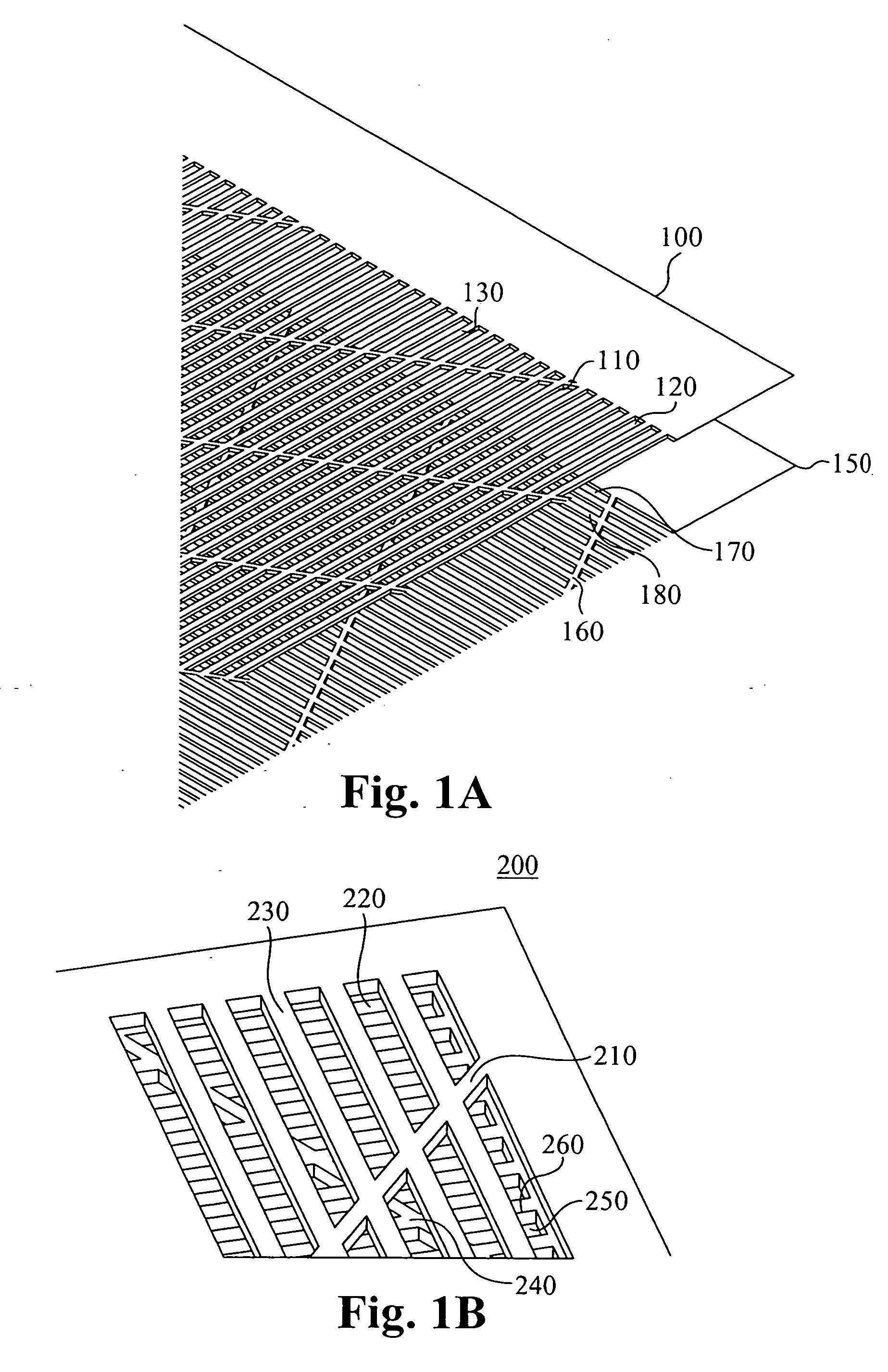
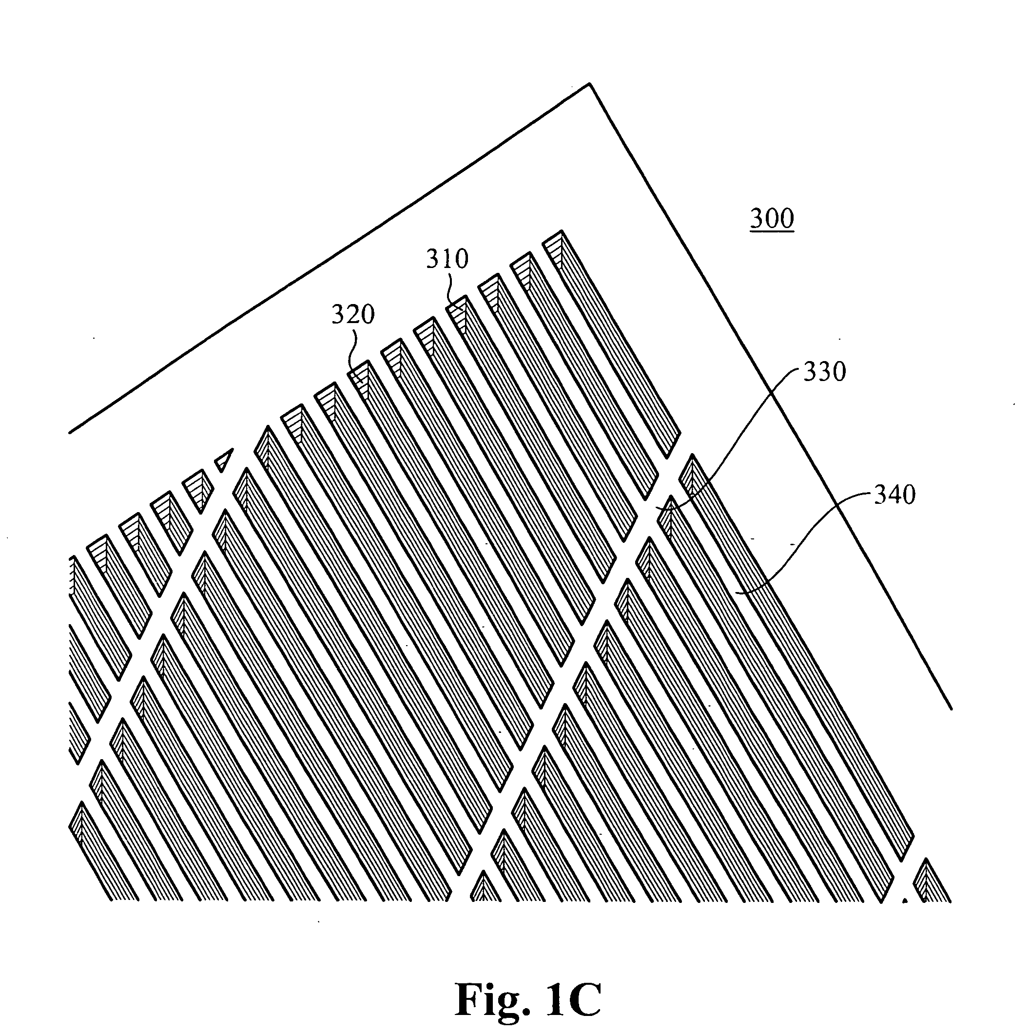
[0059]The present invention describes a method of forming heat conductive layers and coupling a plurality of such layers together to form a three dimensional microstructured region. In accordance with the present invention, the microstructured region comprises micromesh, microchannels, or some other microstructure. FIG. 1A shows a first embodiment of a micro-mesh region, FIG. 2A shows a second embodiment of a micromesh region. FIG. 1C shows a plurality of layers formed and coupled together to create microchannels in accordance with the embodiments of the present invention.

[0060]FIG. 1A shows two windowed layers 100, 150 which have been formed in accordance with the present invention from two heat conductive layers. Preferably, the two heat conductive layers are formed using a wet etching process wherein photo tools are used which determine the locations and patterns of the microscaled apertures 120, 170 of the windowed layers 100, 150. The two windowed layers comprise a plurality of...


PUM

PropertyMeasurementUnit
thicknessaaaaaaaaaa
thicknessaaaaaaaaaa
thicknessaaaaaaaaaa

Abstract

An structure and method of manufacturing a microstructure for use in a heat exchanger is disclosed. The heat exchanger comprises a manifold layer and an microstructured region. The manifold layer comprises a structure to deliver fluid to the microstructured region. The microstructured region is formed from multiple windowed layers formed from heat conductive layers through which a plurality of microscaled apertures have been formed by a wet etching process. The plurality of windowed layers are then coupled together to form a composite microstructure.

Description

RELATED APPLICATION[0001]This application is a continuation-in-part of co-pending U.S. patent application Ser. No. 10 / 680,584, filed Oct. 6, 2003 and entitled “METHOD AND APPARATUS FOR EFFICIENT VERTICAL FLUID DELIVERY FOR COOLING A HEAT PRODUCING DEVICE;” which is a continuation in part of U.S. patent application Ser. No. 10 / 439,635, filed on May 16, 2003 and entitled “METHODS FOR FLEXIBLE FLUID DELIVERY AND HOTSPOT COOLING BY MICROCHANNEL HEAT SINKS,” which claims priority under 35 U.S.C. § 119(e) of the co-pending U.S. Provisional Patent Application Ser. No. 60 / 423,009, filed Nov. 1, 2002 and entitled “METHODS FOR FLEXIBLE FLUID DELIVERY AND HOTSPOT COOLING BY MICROCHANNEL HEAT SINKS,” Ser. No. 60 / 442,382, filed Jan. 24, 2003 and entitled “OPTIMIZED PLATE FIN HEAT EXCHANGER FOR CPU COOLING,” and Ser. No. 60 / 455,729, filed Mar. 17, 2003 and entitled “MICROCHANNEL HEAT EXCHANGER APPARATUS WITH POROUS CONFIGURATION AND METHOD OF MANUFACTURING THEREOF”, all of which are hereby incorp...

Claims


Application Information

Patent Timeline
Patent Type & Authority Applications(United States)
IPC IPC(8): F28F27/02B21D53/02
CPCF04B17/00Y10T29/49353F28D15/0266F28F3/12F28F13/185H01L21/4882H01L23/473F28F2245/04H01L2924/0002F04B19/006Y10T29/49369Y10T29/49366Y10T29/4935H01L2924/00
Inventor DATTA, MADHAVMCMASTER, MARKBREWER, RICKZHOU, PENGTSAO, PAULUPADHAYA, GIRISHMUNCH, MARK
Owner VERTIV CORP
Learn More