Oil Pan and Lubricating Device

a technology of oil pan and lubricating device, which is applied in the direction of lubricant mounting/connection, valve operating means/releasing devices, machines/engines, etc., can solve the problems of slow oil movement difficult to outpour oil from the first chamber into the second chamber through the communication hole, etc., and achieves the effect of simple configuration

Inactive Publication Date: 2008-09-04
TOYOTA JIDOSHA KK
View PDF3 Cites 23 Cited by
  • Summary
  • Abstract
  • Description
  • Claims
  • Application Information

AI Technical Summary

Benefits of technology

[0010]That is, as described above, in removing oil, oil in the first chamber is discharged outside the oil pan after the oil once flows into the second chamber located outside the first chamber. As an oil change is to be made when the operation of the lubricated object is stopped, the temperature of oil in removing is to be lower than that of which when the lubricated object is operated (or when warming up is finished). The double-tank type oil pan has the configuration that when the temperature of oil is low (as the temperature of oil before warming up is finished), the communication of oil between the first chamber and the second chamber through the communicating hole (or the oil communicating channel) is restrained as described above. Therefore, when oil is removed, it is difficult to outpour oil from the first chamber to the second chamber through the communicating hole.
[0065]As described above, according to the present invention, in the double-tank type oil pan and the lubricating device to which the double-tank type oil pan is applied, configuration in which oil can be changed more promptly can be realized by the simple configuration.

Problems solved by technology

However, the above-mentioned conventional type double-tank type oil pan has a problem that the movement of oil from the first chamber into the second chamber is slow when oil is removed from the inside of the oil pan for an oil change and the oil change is not prompt.
Therefore, when oil is removed, it is difficult to outpour oil from the first chamber to the second chamber through the communicating hole.
However, as described above, the size of the drain hole is too small to pass low temperature oil in the second chamber.
Accordingly, when the operation of the lubricated object is stopped and oil is removed (the temperature of the oil is low), it is difficult to outpour the oil from the first chamber to the second chamber through the drain hole.

Method used


Image

  • Oil Pan and Lubricating Device
  • Oil Pan and Lubricating Device
  • Oil Pan and Lubricating Device

Examples


first embodiment

Operation in First Embodiment

[0101]Next, the operation of the oil pan 30 and the lubricating system 40 in this embodiment provided with the above-mentioned configuration will be described.

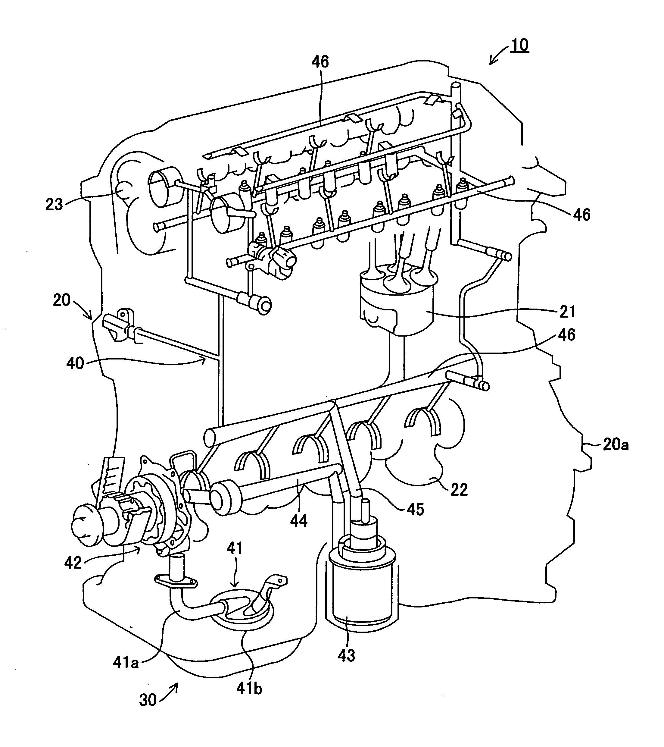
[0102]When the operation of the engine 10 is started, vertical motion of the piston 21 based upon a cyclic motion of the internal combustion engine is converted to a rotational motion of the crankshaft 22, the oil pump 42 sucks oil stored in the first chamber 30a of the oil pan 30 from the suction opening 41b of the strainer 41 by the rotation of a rotor 42a of the oil pump 42 attached to the crankshaft 22, discharges and delivers the sucked oil to the oil transport pipe 44.

[0103]The oil pumped from the oil pump 42 into the oil transport pipe 44 is transported to the oil filter 43 through the oil transport pipe 44 and is filtered by the oil filter 43. The filtered oil is supplied to the oil delivery pipe 46 through the oil supply pipe 45 and is supplied to each moving part such as the piston 21, th...

second embodiment

[0114]FIG. 3 are schematic diagrams for explaining the configuration of a main part of an oil pan 130 in a second embodiment of the present invention, FIG. 3A is a side sectional view, and FIG. 3B is a sectional view viewed along a line B-B in FIG. 3A. The same reference numeral is allocated to an element having the similar action and function to the first embodiment and the description is omitted (also similar in another embodiments described later).

[0115]A communicating pipe for drain 35 as a tubular member is arranged in a lowest part of a bottom panel 31a of an oil pan separator 31 inside a first chamber 30a in the oil pan 130 in this embodiment. The communicating pipe for drain 35 is provided with a pipe base 35a forming a main part of the communicating pipe for drain 35 and a connection part 35b connected to one end of the pipe base 35a and provided so that the connection part vertically pierces the bottom panel 31a of the oil pan separator 31, and the pipe base and the connec...

third embodiment

[0120]FIG. 4 are side sectional views for explaining the configuration of a main part of an oil pan 230 in a third embodiment of the present invention.

[0121]A circular communicating hole for drain 31d is formed in a lowest part of a bottom panel 31a of an oil pan separator 31 in the oil pan 230 in this embodiment. A float valve for drain 36 that can close the communicating hole for drain 31d from the downside is arranged in the oil pan 230.

[0122]The float valve for drain 36 is configured by a base 36a arranged immediately under the communicating hole for drain 31d, a stopper part 36b arranged on the upside of the base 36a and a coupling part 36c that couples the base 36a and the stopper part 36b, and these are integrally formed by foamed resin having sufficiently smaller specific gravity than oil.

[0123]The base 36a is arranged under the bottom panel 31a of the oil pan separator 31 and over a bottom panel 32a of an oil pan cover 32, that is, in a second chamber 30b and under a first ...


PUM


Abstract

An oil pan is provided with an oil pan separator that partitions a first chamber that communicates with a moving part inside a cylinder block and a second chamber outside the first chamber. A communicating hole is provided to a bottom panel of the oil pan separator. The communicating hole is shielded from a strainer.

Description

TECHNICAL FIELD[0001]The present invention relates to an oil pan and a lubricating device to which the oil pan is applied.BACKGROUND ART[0002]For an oil pan applied to a lubricating device for lubricating a lubricated object such as an engine and an automatic transmission with lubricating oil (hereinafter merely called oil), a so-called double-tank type oil pan is well-known. The double-tank type oil pan is provided with a first chamber that communicates with the lubricated object by being opened toward the lubricated object, a second chamber that is adjacent to the first chamber and communicates with the first chamber via an oil communicating channel and a partition provided between the first chamber and the second chamber.[0003]For related art of this type of double-tank type oil pan, a double-tank type oil pan disclosed in JP-A No. 222012 / 2003 can be given.[0004]This conventional type oil pan is provided with an oil pan separator having a concave part for forming the almost whole...

Claims


Application Information

Patent Timeline
Patent Type & Authority Applications(United States)
IPC IPC(8): F16N31/00
CPCF01M5/007F01M11/0004F01M2011/007F01M2011/0045F01M2011/0037Y10T137/7404Y10T137/7436F01M5/00F01M11/00F01M11/03
Inventor MORI, TAIICHIKOBAYASHI, HIDEOARISAWA, KATUHIKOYAMADA, KENICHIYAMASHITA, YOSHIOHAYASHI, KUNIHIKO
Owner TOYOTA JIDOSHA KK
Why Eureka
Try Eureka