Segmented ion trap mass spectrometry

a mass spectrometry and segmented ion technology, applied in the field of segmented ion trap mass spectrometry, can solve the problems of reducing the efficiency of ions entering and exiting the mass analyzer, the difficulty of trapping ions in the mass analyzer, and the reduction of sensitivity, so as to achieve good collisional energy removal and consequent capture efficiency without compromising analytical scan resolution or speed

Inactive Publication Date: 2008-09-04
THERMO FINNIGAN
View PDF14 Cites 29 Cited by
  • Summary
  • Abstract
  • Description
  • Claims
  • Application Information

AI Technical Summary

Benefits of technology

[0011]In broad terms, a mass analyzer of the current invention allows for ion traps to be used of a lower pressure than can typically be utilized without the use of intermediate configurations between the ion source and the mass analyzer.
[0012]In one broad form of the invention, the ion trap effectively partitions the ion capture function to a first segment of the ion trap, and the analytical scan function to the second segment of an ion trap, thereby facilitating good collisional energy removal and consequent capture efficiency without compromising analytical scan resolution or speed.

Problems solved by technology

Typically, when combined with a mass analyzer such as a TOF or an ion trap mass analyzer, the ions produced by the MALDI ionization process have such a wide range of kinetic energies, some of which are relatively high in value, that it is difficult to trap the ions in the mass analyzer.
When a Fourier Transform Mass Spectrometer (FTMS) or an ion trap type mass spectrometer is utilized with ions produced via the MALDI process, the wide range of kinetic energy in the ions reduces the efficiency by which ions travel into and become trapped in FT and ion trap type mass spectrometers, consequently resulting in decreased sensitivity.
Each pumping stage has cost associated with it, and brings with it its own set of considerations and issues.
The result is that the ion signal at the detector has a broad peak, and consequently the mass resolution, which is a measure of an instruments capability to produce separate signals (isotopic peaks) from ions of similar mass, is limited.
The ion mirrors or reflectrons have costs associated with them, and once again bring with them their own set of considerations and issues.
However, the existence of the additional interface components add an additional layer of complexity to the overall mass spectrometry system, additional physical components and an additional expense.

Method used


Image

  • Segmented ion trap mass spectrometry
  • Segmented ion trap mass spectrometry
  • Segmented ion trap mass spectrometry

Examples


Embodiment Construction

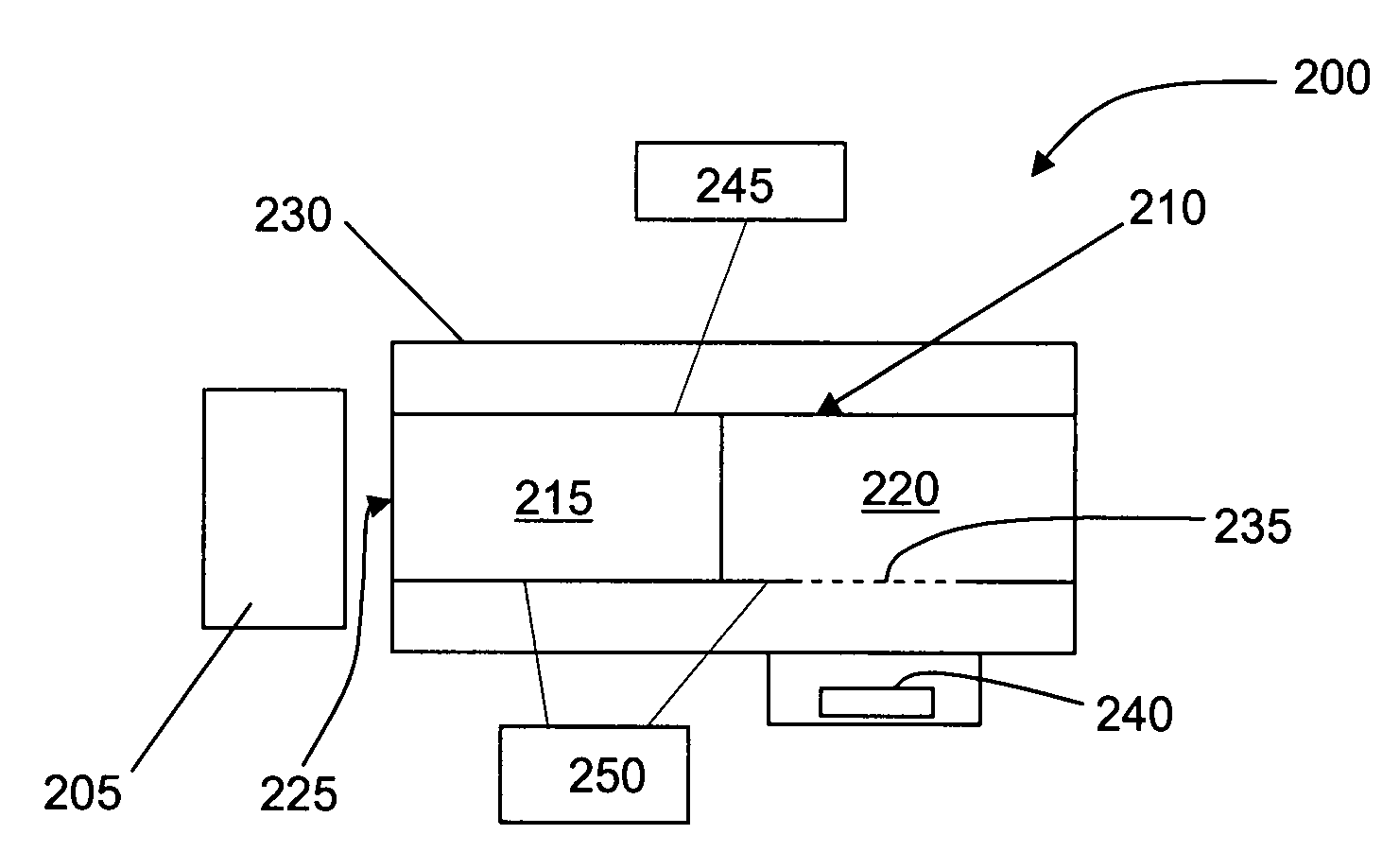
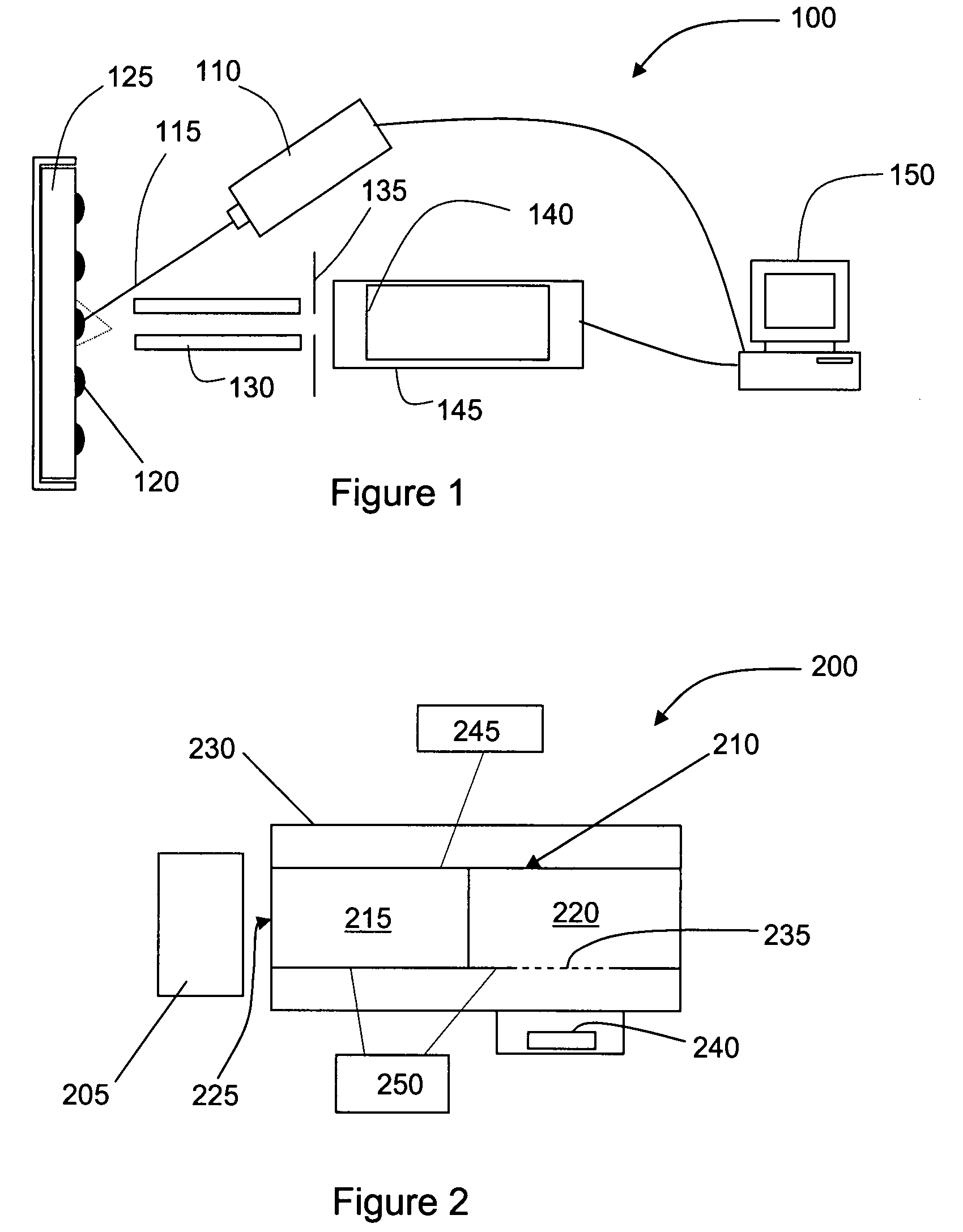
[0025]FIG. 2 is a schematic depiction of the major components of a mass spectrometer system 200 comprising a laser-based ionization source 205 and an ion trap 210 in accordance with an embodiment of the present invention. The ion trap configuration 210 of the present invention is configurable to provide a plurality of (at least two) substantially discrete trapping volumes or segments 215, 220, each of these segments or combination of segments being electrically isolated from one another when an electrical and / or magnetic isolation mechanism is activated, and capable of acting in combination as a continuous device when the segments are “assembled” or the electrical / magnetic isolation means has been deactivated. The ion trap configuration must enable the interior volume of the ion trap 210 to be physically subdivided such that ions may be spatially trapped in one or more of the discrete trapping regions 215, 220 of the ion trap 210.

[0026]The multi-segment configuration of the ion trap...


PUM


Abstract

An ion trap is provided with at least two discrete trapping regions or segments. Both segments are located in a vacuum chamber of a mass spectrometer system. An entrance of the ion trap is disposed downstream to a laser based ionization source to receive the ions with a wide range of kinetic energies that have been generated by the laser-based ionization source. Once sufficient ions have been accumulated in the first segment and sufficient time has passed to cool the ions, they are transferred to the second segment and ultimately ejected through an aperture or slot to a detector arrangement to produce a mass spectrum.

Description

FIELD OF THE INVENTION[0001]This invention relates particularly to mass analyzers that utilize laser-based ionization sources.BACKGROUND OF THE INVENTION[0002]In recent years, matrix assisted laser desorption ionization (MALDI) mass spectrometry, a technique that provides minimal fragmentation and high sensitivity for the analysis of a wide variety of fragile and non-volatile compounds, has become widely used. In its simplest form, the MALDI technique involves depositing the sample (analyte) and a matrix dissolved in a solvent as a spot on a target plane. After the solvent has evaporated, the mixture of sample and matrix is left on the sample plate. This is inserted into a mass spectrometer where a pulse from a laser irradiates the matrix and causes it to evaporate. The sample is carried with the matrix, ionized, and analyzed by the mass spectrometer. MALDI sources are typically used with spectrometers that allow for storage of ions, such as ion trap mass spectrometers and fourier t...

Claims


Application Information

Patent Timeline
Patent Type & Authority Applications(United States)
IPC IPC(8): H01J49/26
CPCH01J49/004H01J49/42H01J49/164
Inventor KOVTOUN, VIATCHESLAV V.
Owner THERMO FINNIGAN
Why Eureka
Try Eureka