Methods and apparatus of ion mobility spectrometer

a spectrometer and mobility technology, applied in the field of methods and apparatus of ion mobility spectrometer, can solve the problems of limited portability, high power consumption, and significant limitations of the spectrometer performance, and achieve the effects of reducing tofims, increasing the effective temperature of ions, and high r

Active Publication Date: 2008-09-04
EXCELLIMS CORP
View PDF14 Cites 45 Cited by
  • Summary
  • Abstract
  • Description
  • Claims
  • Application Information

AI Technical Summary

Benefits of technology

[0007]In some embodiments of the present invention, the energy source that supplies non-thermal energy to the ions is a radio frequency (RF) electric field. Therefore, an EE-IMS uses RF electric field to heat up ions non-thermally. Non-thermally means that the ion energy is NOT in equilibrium with the background gas. The increased energy of the ions provides a means to modify the linear drift mobility in order to minimize the problems with TOFIMS. The EE-IMS of the invention uses high RF electric fields in order to increase the effective temperature of the ions, in one aspect to minimize the adverse chemical and physical behavior of the ions due to humidity or other interferences in the environment. It may also use a combination of DC fields and RF fields, such that the ion separation is performed using the DC field, but the RF fields are used to modify the chemistry and prevent some of the problem associated with present day devices.
[0008]Alternatively, the RF heating method during ion transportation and mobility based separation can be used for FAIMS, DMS and/or other derived forms where the RF electric field is applied in the direction that is perpendicular (or other angles) to the (asymmetr

Problems solved by technology

In many cases, in a less-than ideal operating environments (in particular those with high humidity or other site-specific interferences), the spectrometer performance is significantly limited.
Unfortunately, the use of high temperature drift tubes in IMS devices results in high power consumption, limited portability and other operational disadvantages, includ

Method used


Image

  • Methods and apparatus of ion mobility spectrometer
  • Methods and apparatus of ion mobility spectrometer
  • Methods and apparatus of ion mobility spectrometer

Examples


Embodiment Construction

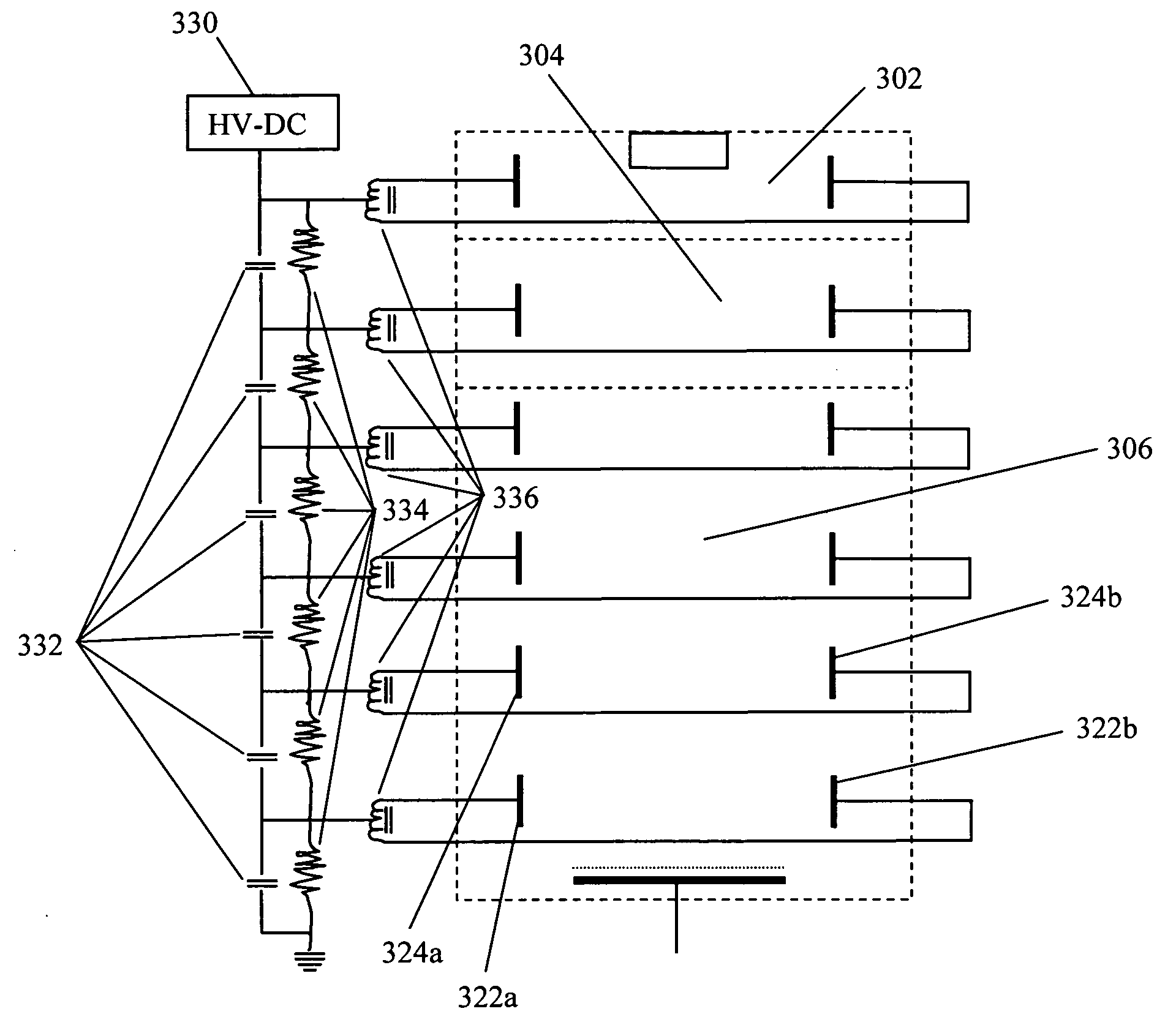
[0027]The term ion mobility separator, and ion mobility spectrometer, and ion mobility based spectrometers are used interchangeably in this invention, often referred to as IMS, including time-of-flight (TOF) IMS, differential mobility spectrometers (DMS), field asymmetric ion mobility spectrometers (FAIMS) and their derived forms. A time of flight ion mobility spectrometer and their derived forms refers to, in its broadest sense, any ion mobility based separation device that characterize ions based on their time of flight over a defined distance. A FAIMS, a DMS, and their derived forms separate ions based on their ion mobility characteristics under high values of normalized electric field.

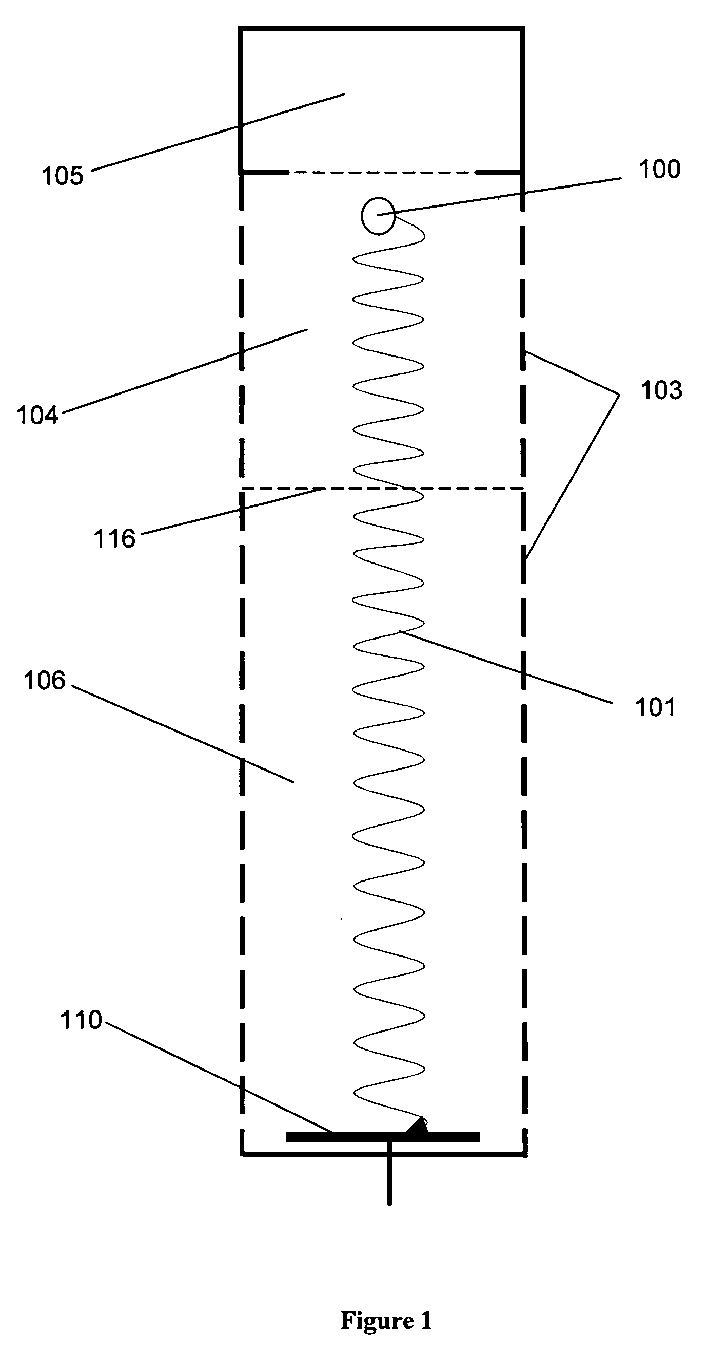
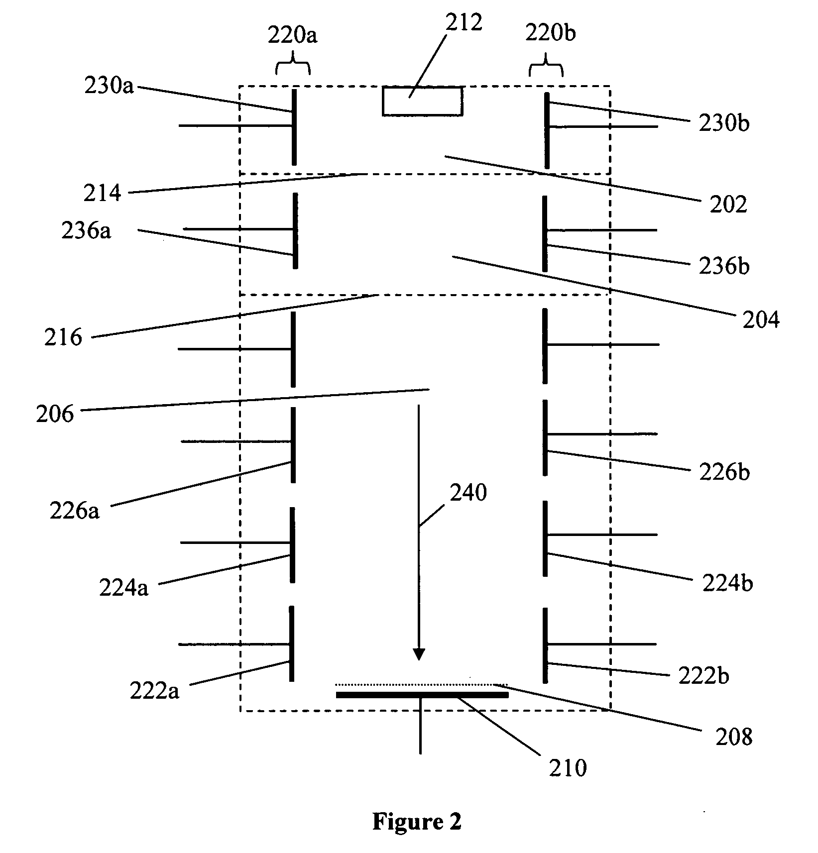
[0028]The systems and methods of the present inventions may make use of “drift tubes.” The term “drift tube” is used herein in accordance with the accepted meaning of that term in the field of ion mobility spectrometry. A drift tube is a structure containing a neutral gas through which ions are mov...


PUM


Abstract

The present invention describes apparatuses and methods that provide energy to ions in a non-thermal manner. The elevated ion energy minimizes or eliminates interferences due to clustering with polar molecules, such as water. The energized ions are separated in an ion mobility spectrometer. During the ion transportation and separation process, the elevated energy level of ions prevents them from clustering with neutral molecule inside the spectrometer. The additional electric field component only causes ions to reach elevated energy level, whereby the spectrometer can preserve its normal performance, meanwhile avoiding interference from water and other neutral molecules. A RF electric field is applied to the ions in ionization, reaction and separation region of ion mobility spectrometers.

Description

CROSS-REFERENCE TO RELATED APPLICATIONS[0001]The present application claims the benefit of and priority to corresponding U.S. Provisional Patent Application No. 60 / 888,172, filed Feb. 5, 2007 respectively, the entire content of the application is herein incorporated by reference.BACKGROUND OF THE INVENTION[0002]Ion mobility spectrometers (IMS) are widely used in field chemical analysis. IMS separate ionic species based on their ion mobility in a given media (either gas or liquid). Recent development of the IMS technology results in two forms of IMS instruments and systems. The time-of-flight (TOF) IMS separate ions based on their steady state ion mobilities under constant electric field. High resolving power with IMS has been achieved with the TOF-IMS instruments. Alternatively, devices that separate ions based their mobility changes under high field conditions, such as field asymmetric ion mobility spectrometer (FAIMS) or differential mobility spectrometer (DMS), can also be used. ...

Claims


Application Information

Patent Timeline
IPC IPC(8): H01J49/28H01J49/00
CPCG01N27/624G01N27/622
Inventor WU, CHINGBROMBERG, LESLIE
Owner EXCELLIMS CORP
Why Eureka
Try Eureka