Charged Particle System

a particle system and charge technology, applied in the field of charge particle system, to achieve the effect of optimum imaging performance and small

a particle system and charge technology, applied in the field of charge particle system, to achieve the effect of optimum imaging performance and small

US20080210887A1Active Publication Date: 2008-09-04CARL ZEISS SMT GMBH

Image

  • Charged Particle System
  • Charged Particle System
  • Charged Particle System

Examples


Embodiment Construction

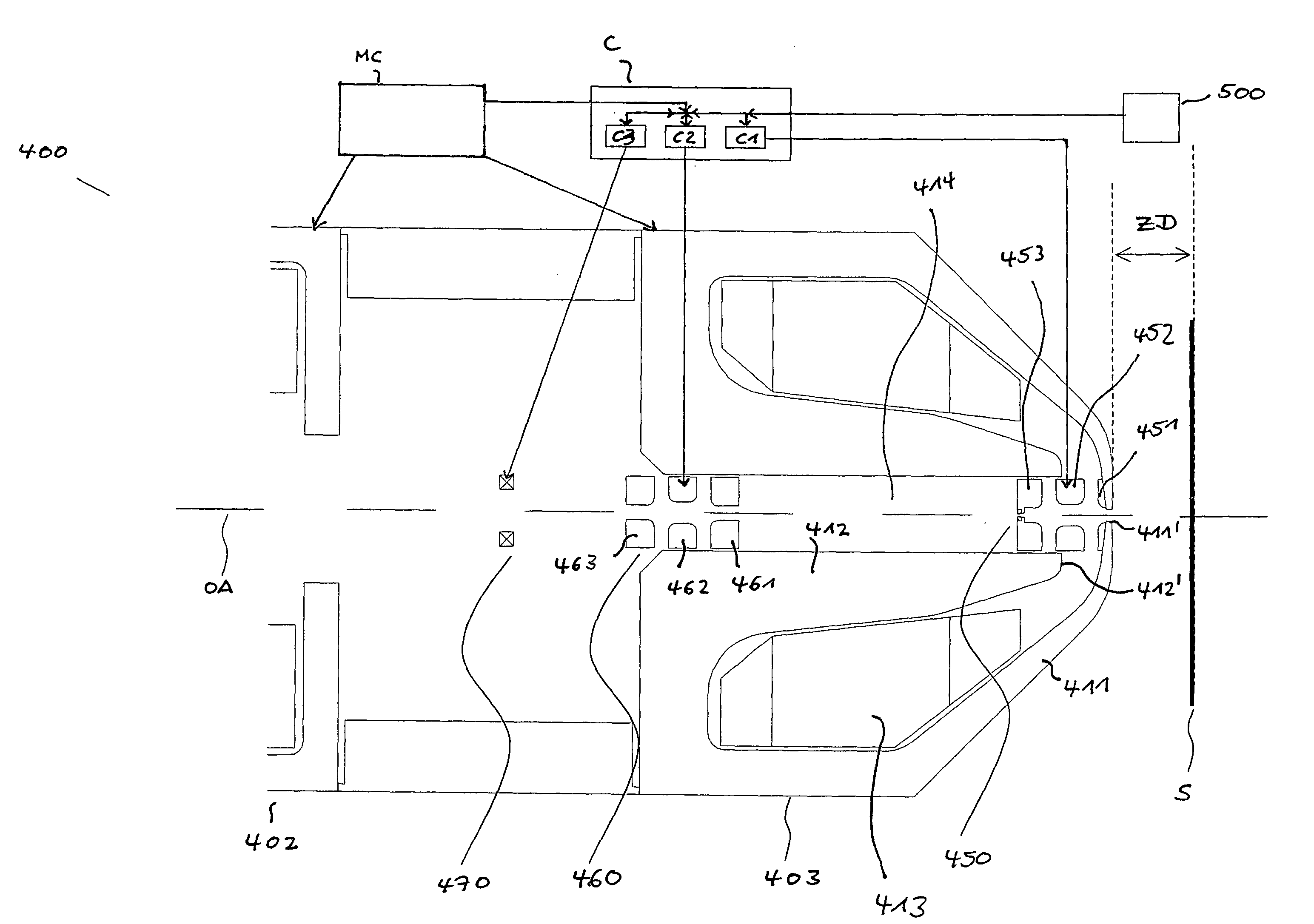
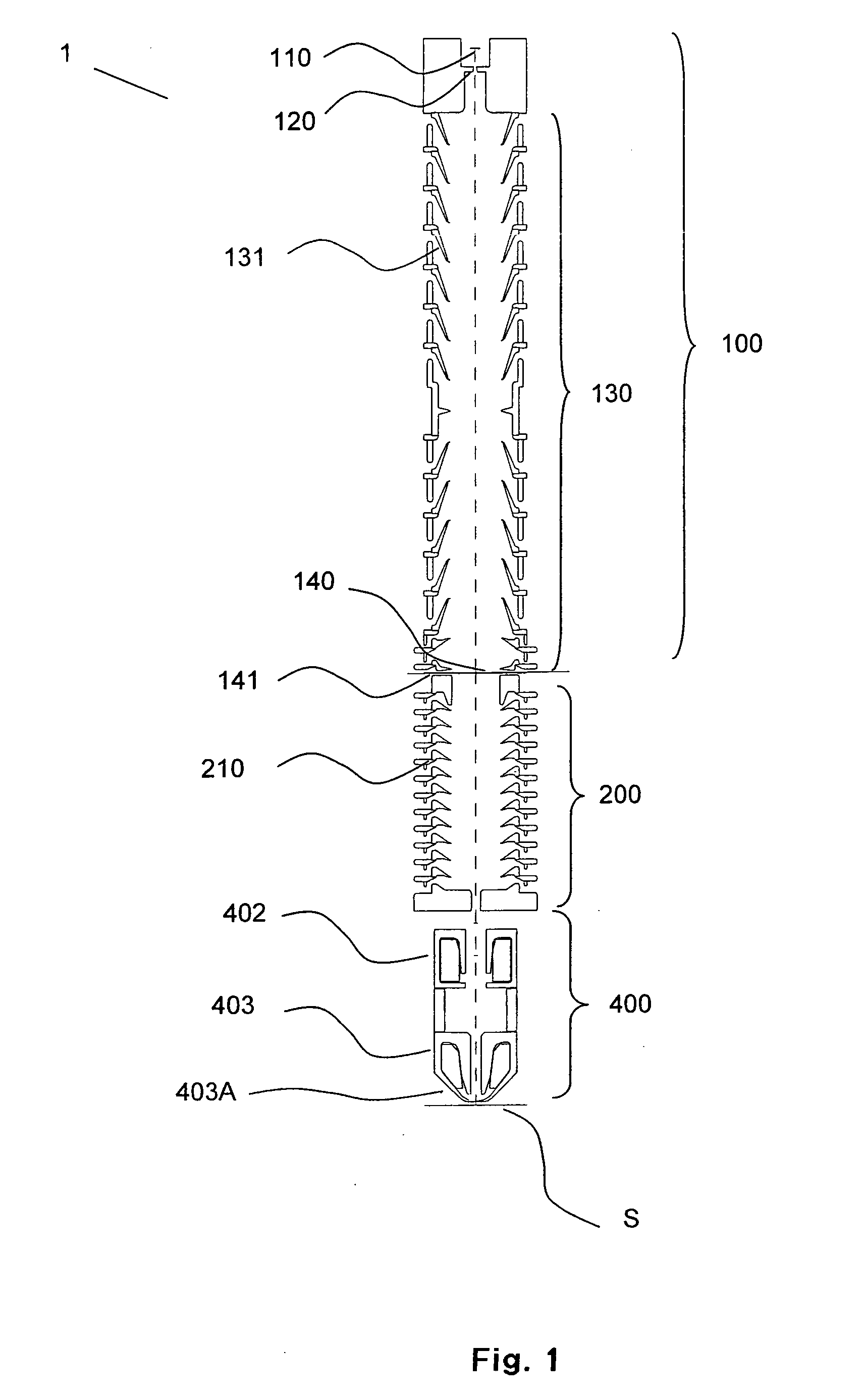
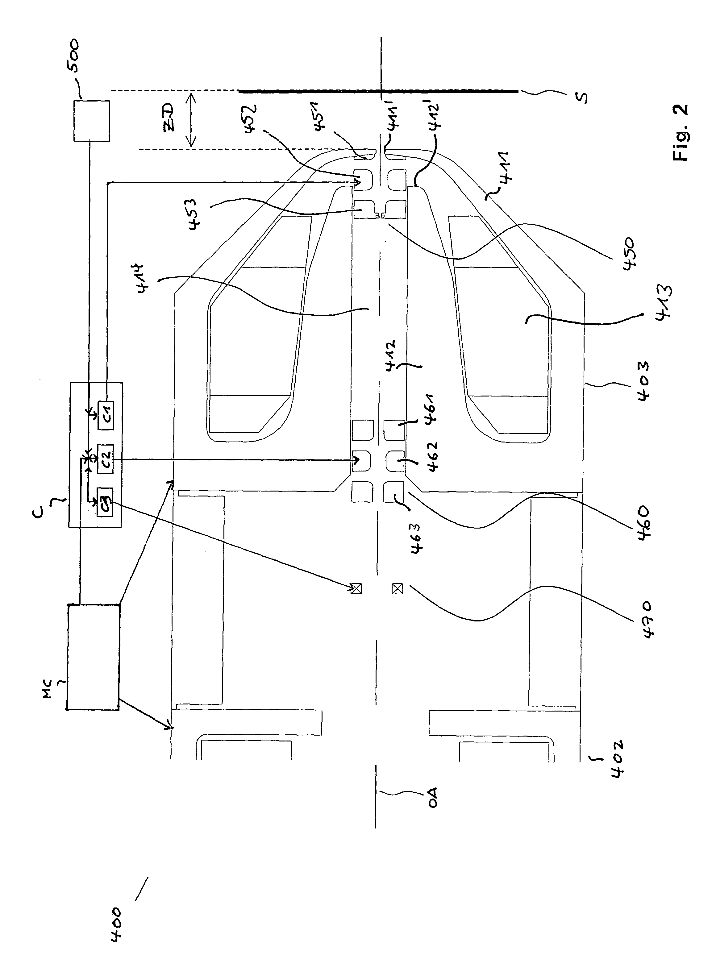
[0085]In FIG. 1, an embodiment of a charged particle lithography system according to the present invention is illustrated in a schematic and simplified manner. Lithography system 1 comprises, in a direction in which the charged particles would generally travel, a beamlet generating arrangement 100, and a particle-optical projection system comprising an electrostatic lens 200 and electromagnetic focussing lens arrangement 400. The beamlet generating arrangement 100 comprises a charged particle source 110, an extraction system 120 and a condenser lens 130. The condenser lens 130 comprises a stack of electrodes 131. The beamlet generating system 100 further comprises a pattern defining structure 140 held by a mounting frame 141. The pattern defining structure 140 generally comprises a multi-aperture plate, and may be a blanking aperture array as described above. The electrostatic lens arrangement 200 comprises a plurality of electrode elements 210 which are arranged in series along the...


PUM


Abstract

A charged particle system comprises a particle source for generating a beam of charged particles and a particle-optical projection system. The particle-optical projection system comprises a focusing first magnetic lens (403) comprising an outer pole piece (411) having a radial inner end (411′), and an inner pole piece (412) having a lowermost end (412′) disposed closest to the radial inner end of the outer pole piece, a gap being formed by those; a focusing electrostatic lens (450) having at least a first electrode (451) and a second electrode (450) disposed in a region of the gap; and a controller (C) configured to control a focusing power of the first electrostatic lens based on a signal indicative of a distance of a surface of a substrate from a portion of the first magnetic lens disposed closest to the substrate.

Description

BACKGROUND OF THE INVENTION[0001]1. Field of the Invention[0002]The invention relates to a charged particle system, such as a lithography system.[0003]2. Brief Description of Related Art[0004]Lithographic processes are commonly used in the manufacture of semiconductor elements, such as integrated circuits (ICs), LSIs, liquid crystal elements, micro-patterned members and micromechanical components.[0005]A charged particle lithography system generally comprises a beam generating system with a charged particle source, a patterning device and a particle-optical projection system. One or more charged particle beams generated by the beam generating system are generally directed to be incident on the patterning device adapted to endow the incident beam with a pattern or, in other words, generate a pattern of charged particle beamlets. The pattern is conveyed by charged particle beamlets transmitted through the patterning device which are subsequently focused and imaged, usually at a reduce...

Claims


Application Information

Patent Timeline
04 Sep 2008
Publication
US20080210887A1
IPC
H01J37/147; H01J37/21; H01J37/317
CPC
B82Y10/00; B82Y40/00; H01J37/147; H01J2237/24578; H01J37/3174; H01J2237/0492; H01J37/21
Inventors
BUSCHBECK, HERBERT; PLATZGUMMER, ELMAR