Medical Device with Transcutaneous Cannula Device

a technology of cannula and medical device, which is applied in the direction of intravenous devices, catheters, other medical devices, etc., can solve the problems of increasing complexity, affecting the effect of piercing the tissue with the needle, so as to achieve less damage

Inactive Publication Date: 2008-09-04
NOVO NORDISK AS
View PDF99 Cites 187 Cited by
  • Summary
  • Abstract
  • Description
  • Claims
  • Application Information

AI Technical Summary

Benefits of technology

[0016]Correspondingly, a medical device is provided, comprising a lower surface adapted for application towards the skin of a subject, a transcutaneous fluid transport device having a distal end portion adapted to be arranged through the skin of the subject and having a distal fluid outlet, and a fluid inlet portion in fluid communication with the distal end portion. The lower surface may be generally planar or it may have another suitable configuration. The fluid transport device comprises an insertion needle and a cannula disposed on (or in) and being axially moveable relative to the insertion needle, the cannula and insertion needle further being moveable relative to the lower surface. The insertion needle comprises a distal end adapted to penetrate the skin of the subject, and a fluid inlet arranged proximally from the cannula, the cannula forming the distal end portion. A seal is provided between the cannula and the insertion needle (i.e. on the inner or outer side of the cannula) allowing fluid to be transported from the fluid inlet to the distal fluid outlet preventing an escape of fluid between the needle and the cannula. In accordance with the invention the fluid transport device has a number of states. More specifically, an initial state in which the cannula and the insertion needle are retracted relative to the lower surface, the fluid inlet being arranged at an initial position, an intermediate state in which the cannula and the insertion needle are extended relative to the lower surface with the distal end of the insertion needle projecting relative to the distal end of the cannula thereby allowing the fluid transport device to be introduced through the skin of the subject, and an extended state in which the cannula extends relative to the lower surface with the distal end of the insertion needle being retracted relative to the distal end of the cannula, the fluid inlet being arranged at a retracted position proximally of the initial position. The insertion needle may be retracted relative to the distal end of the cannula (e.g. the insertion needle may be retracted relative to the lower surface, or the cannula may be extended without the insertion needle being extended at the same speed) before the cannula has been fully extended relative to the housing, this allowing a blunt cannula to serve as the leading element during insertion through a portion of the sub-cutis, this potentially causing less damage.
[0017]As appears, this arrangement allows the fluid inlet to be connected to a fluid supply when it is moved from its initial to its retracted position, thereby allowing the insertion needle in a simple way to serve also as a fluid communication between the moveable cannula and the fluid supply. By connecting the fluid inlet of the insertion needle to the fluid supply after the insertion needle has been utilized to insert the cannula, it is provided that the insertion needle can move freely during insertion without being connected to an additional structure.

Problems solved by technology

The first class comprises durable infusion pumps which are relatively expensive pumps intended for 3-4 years use, for which reason the initial cost for such a pump often is a barrier to this type of therapy.
Although this configuration provides a simple and cost-effective solution, the actual user-performed piercing of the tissue with the needle is often problematic as people who are not experts in medicine are usually insufficiently practised to place such a needle correctly and they often suffer from a fear of the likely pain.
Although the automatic needle insertion means adds convenience for the user and may serve to overcome needle fear, such means also adds to the complexity and thus to the cost of the device, they may reduce the reliability, just as they may add to the bulkiness of the device.

Method used


Image

  • Medical Device with Transcutaneous Cannula Device
  • Medical Device with Transcutaneous Cannula Device
  • Medical Device with Transcutaneous Cannula Device

Examples


Embodiment Construction

[0045]When in the following terms as “upper” and “lower”, “right” and “left”, “horizontal” and “vertical” or similar relative expressions are used, these only refer to the appended figures and not to an actual situation of use. The shown figures are schematic representations for which reason the configuration of the different structures as well as there relative dimensions are intended to serve illustrative purposes only.

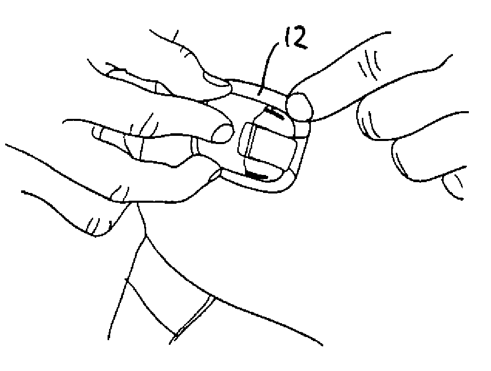
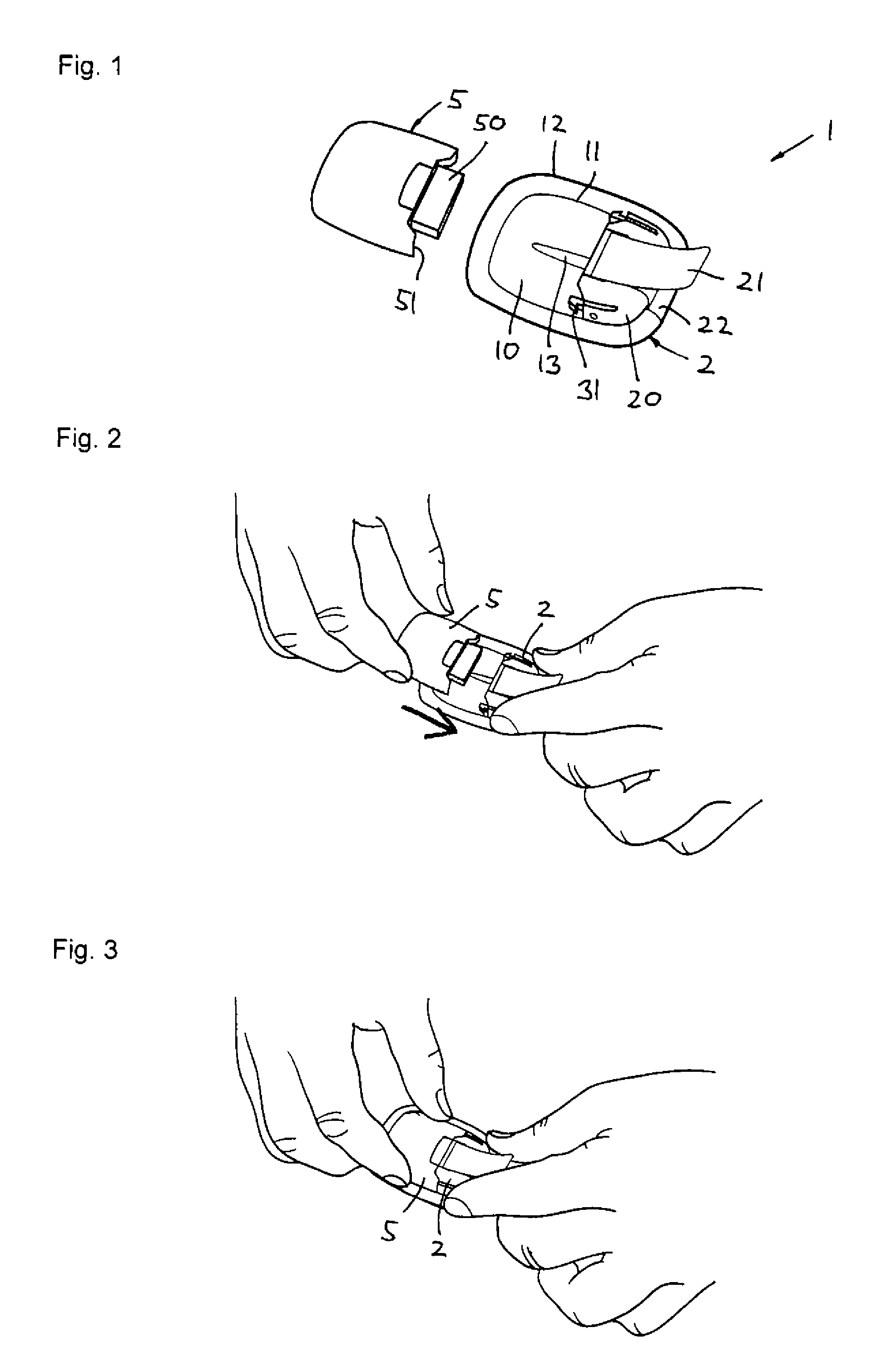
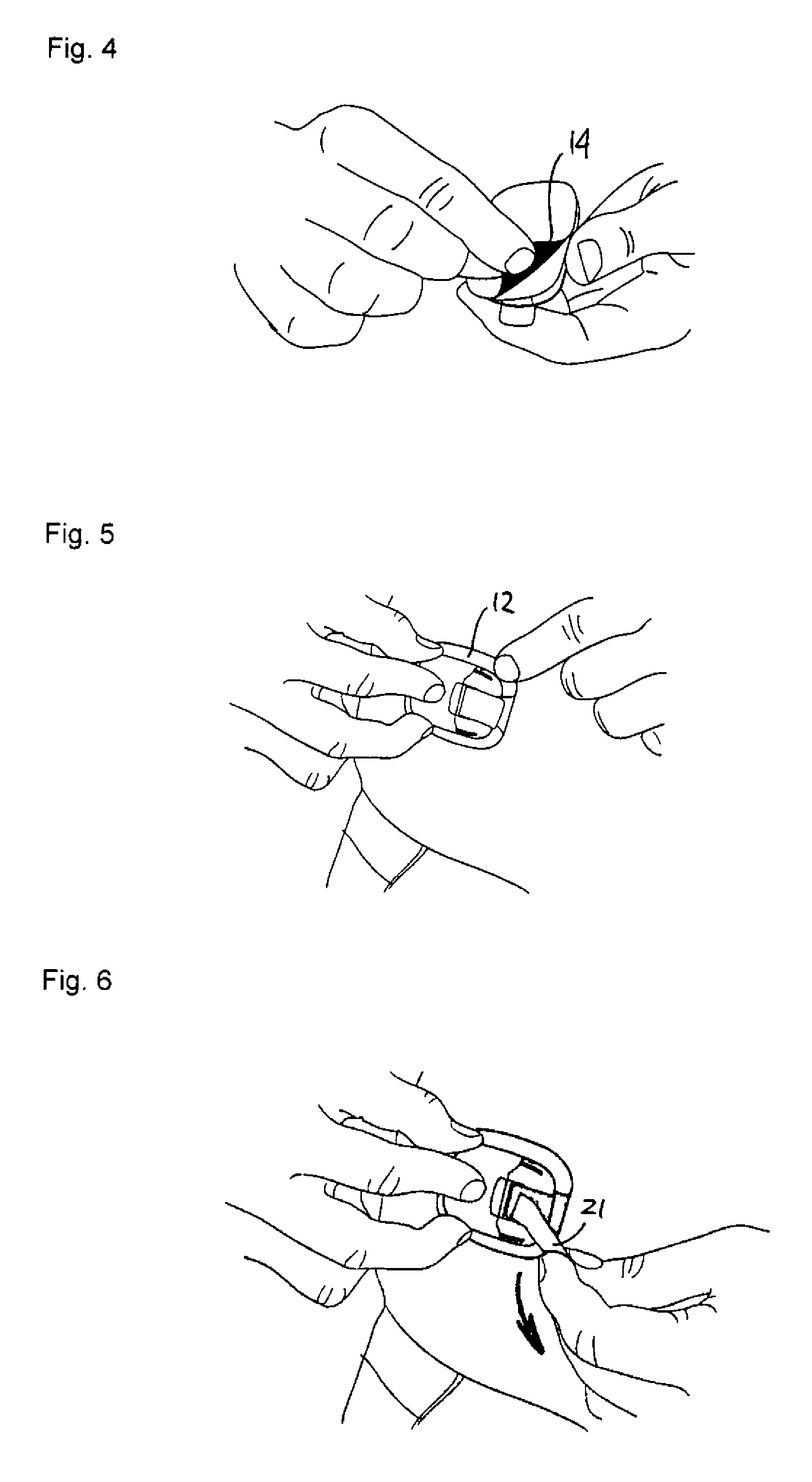
[0046]Firstly, with reference to FIGS. 1-12 an embodiment of a drug delivery device will be described focusing primarily on the directly user-oriented features. The delivery device is shown as an example of a type of device in which the present invention advantageously may be implemented, however, the described modular delivery can be considered to be “generic” in respect of the transcutaneous device actually used, e.g. a needle or a cannula.

[0047]The transcutaneous device unit 2 comprises a transcutaneous device in the form of a cannula and an associated insertion ...


PUM


Abstract

The present invention generally relates to the insertion of a transcutaneous device of the type comprising a cannula (651) and a therein moveably arranged insertion needle (661), as well as the connecting of such a transcutaneous device with a fluid supply. Thus, a device is provided comprising an insertion needle and a cannula disposed on and being axially moveable relative to the insertion needle, the insertion needle comprising a proximal fluid inlet, a seal (655) being provided between the cannula and the insertion needle allowing fluid to be transported from the fluid inlet to the distal fluid outlet, wherein the insertion needle after having been used to insert the cannula is arranged at a retracted position proximally of the initial position, thereby allowing the fluid inlet to be connected to a fluid supply when it is moved from its initial to its retracted position.

Description

[0001]The present invention generally relates to the insertion of a transcutaneous device, especially of the type comprising a cannula and a therein moveably arranged insertion needle, as well as the connecting of such a transcutaneous device with a fluid supply.BACKGROUND OF THE INVENTION[0002]In the disclosure of the present invention reference is mostly made to the treatment of diabetes by injection or infusion of insulin, however, this is only an exemplary use of the present invention.[0003]Portable drug delivery devices for delivering a drug to a patient are well known and generally comprise a reservoir adapted to contain a liquid drug and having an outlet in fluid communication with a hollow infusion needle, as well as expelling means for expelling a drug out of the reservoir and through the skin of the subject via the hollow needle. Such devices are often termed infusion pumps.[0004]Basically, infusion pumps can be divided into two classes. The first class comprises durable i...

Claims


Application Information

Patent Timeline
Patent Type & Authority Applications(United States)
IPC IPC(8): A61M5/142A61M5/14
CPCA61M5/14248A61M5/16877A61M2005/1426A61M2005/14252A61M25/0606
Inventor THORKILD, AHM
Owner NOVO NORDISK AS
Why Eureka
Try Eureka