Smart Vortex Generator, and Aircraft, Vessel, and Rotary Machine Being Equipped with the Same

a generator and smart technology, applied in machines/engines, machine/engines, air-flow influencers, etc., can solve the problems of enlarged drag, insufficient lift force, and decreased maneuverability

Inactive Publication Date: 2008-09-11
NAGOYA UNIVERSITY
View PDF10 Cites 39 Cited by
  • Summary
  • Abstract
  • Description
  • Claims
  • Application Information

AI Technical Summary

Benefits of technology

[0016]The present invention is one which has been done in view of the aforementioned circumstances, and its technical assignment to be solved is to provide a smart vortex generator, which is a vortex generator exhibiting a multi-directional characteristic depending on a temperature change, and the like; in which no energy supply from the outside is required; whose structure is simple; in which failures are less likely to occur; which makes the repairs and maintenance as well as the installation to existing wings, and so forth, easy; and to provide an aircraft, a vessel and a rotary machine which are equipped with the same.

Problems solved by technology

However, when the wing's angle of attack increases beyond the limit, or when the airfoil camber becomes larger too much, a flow separates from a wing surface so that a drag becomes larger and additionally no sufficient lift force can be obtained, and thereby there is a fear that the maneuverability might degrade.
By the way, while a vortex generator demonstrates such a function that it suppresses a flow separation from a wing surface upon takeoff and landing when a wing's angle of attack or an airfoil camber becomes larger, there is a disadvantage that, upon cruising when a wing's angle of attack or an airfoil camber becomes smaller, it has disturbed a flow on a wing surface by means of vortexes generated by the vortex generator and has enlarged a drag by means of turbulent flow.
The phenomenon that, upon cruising which takes the longest time in flight routes, a drag has been enlarged by means of the vortex generator results in a greater problem from the viewpoint of the maneuvering performance and fuel consumption of aircraft.
However, in this instance, since the fin portion 94 has come to generate vortexes on the wing surface even upon cruising, it brings about the enlargement of drag.
Accordingly, the techniques set forth in aforementioned Patent Literature Nos. 1 and 2 require an energy supply from the outside, and are consequently associated with such problems that their apparatuses are complicated structurally; failures are likely to occur in the electric systems, and the like; and moreover their repairs and maintenance as well as their installations to existing wings are troublesome.

Method used


Image

  • Smart Vortex Generator, and Aircraft, Vessel, and Rotary Machine Being Equipped with the Same
  • Smart Vortex Generator, and Aircraft, Vessel, and Rotary Machine Being Equipped with the Same
  • Smart Vortex Generator, and Aircraft, Vessel, and Rotary Machine Being Equipped with the Same

Examples


first embodiment

Mode

[0143]This First Embodiment Mode is one which relates to a smart vortex generator which demonstrates a bidirectional characteristic depending on a temperature change of fluid.

embodiment mode 1

[0144]This Embodiment Mode 1 is one which relates to a smart vortex generator which demonstrates a bidirectional characteristic by means of a combination of a shape memory alloy's one-way shape memory effect and a bias force, which comprises a spring force and a fluidic force. Moreover, this embodiment mode is one in which the smart vortex generator according to the present invention is applied to an airplane, one of aircraft; more concretely, to an airplane (or a jet plane, for instance) which flies at high altitude.

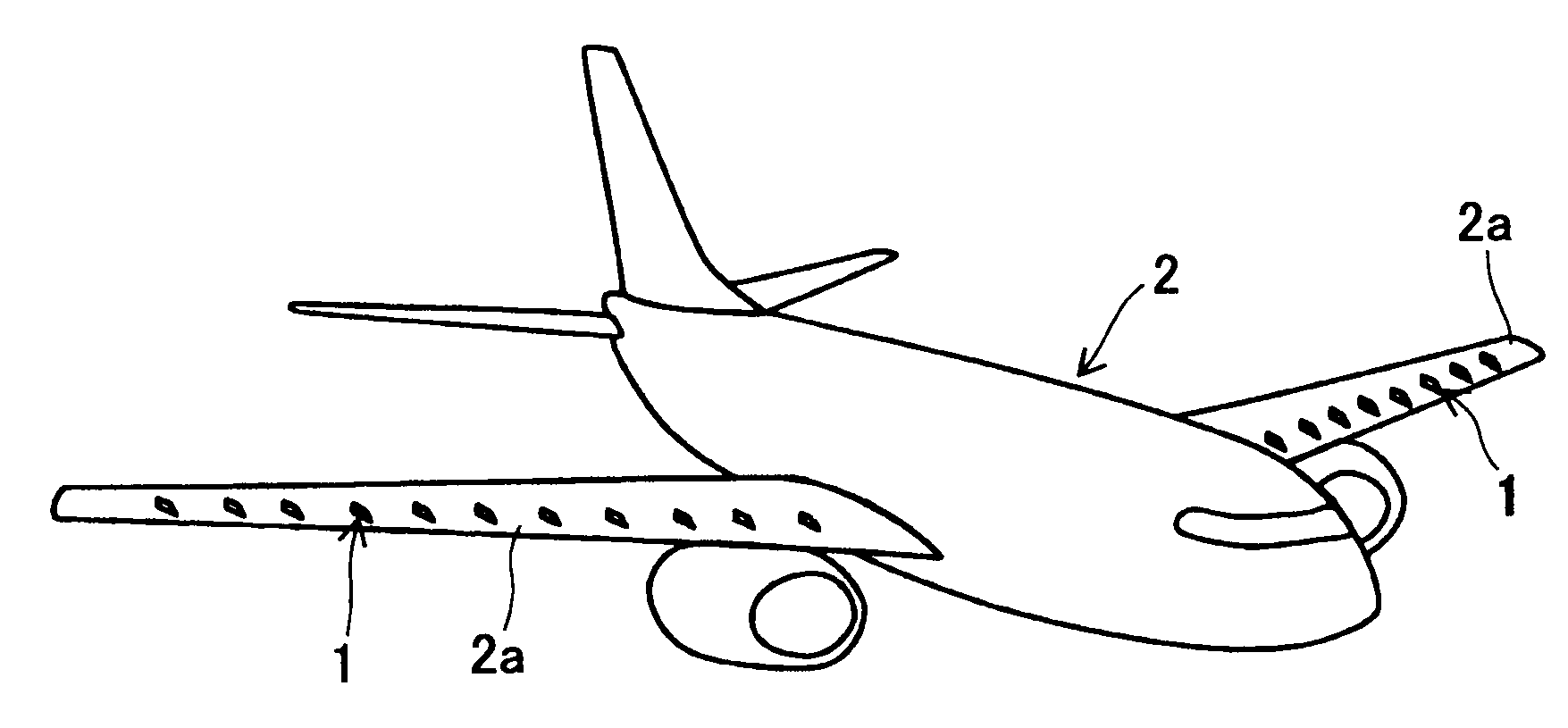
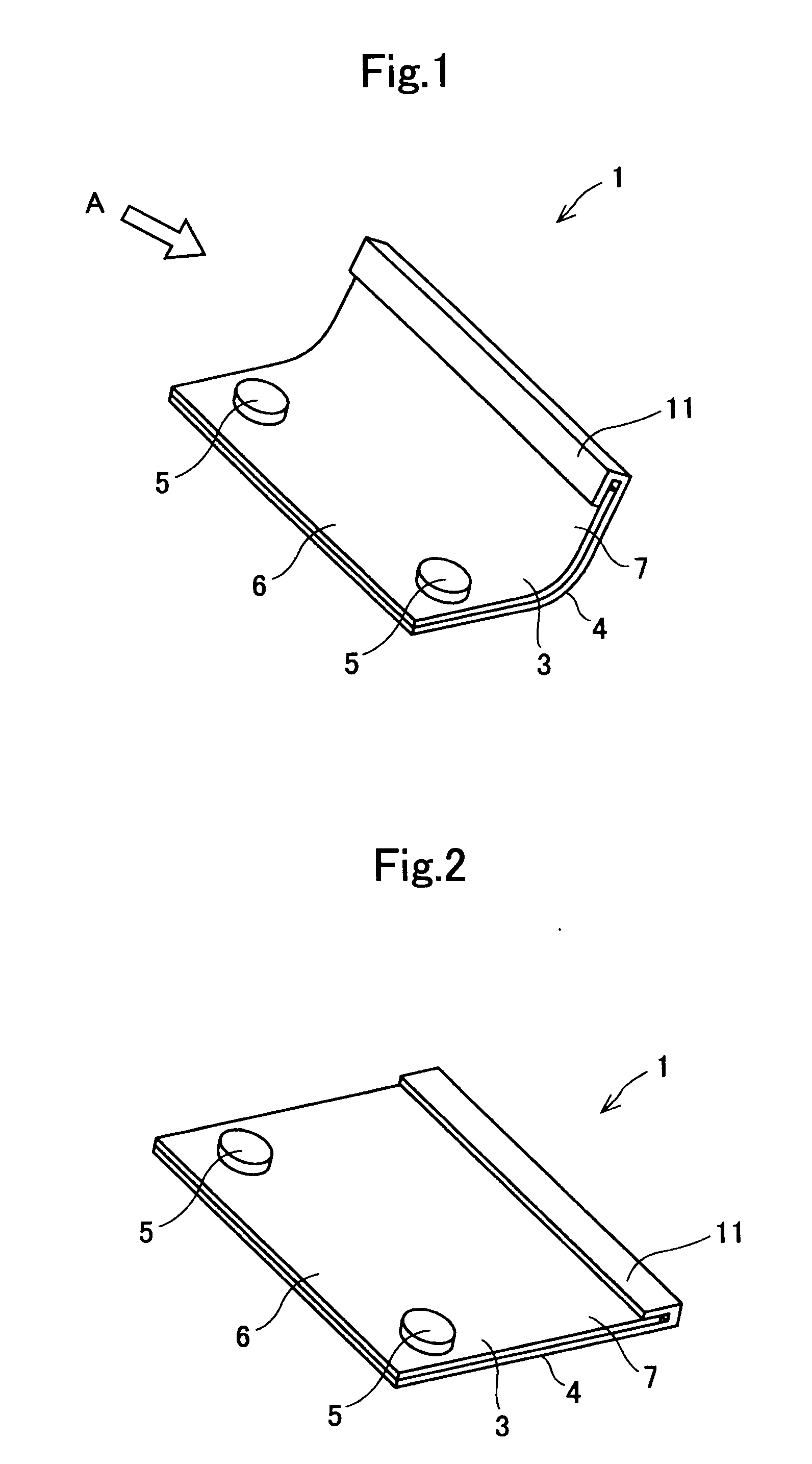
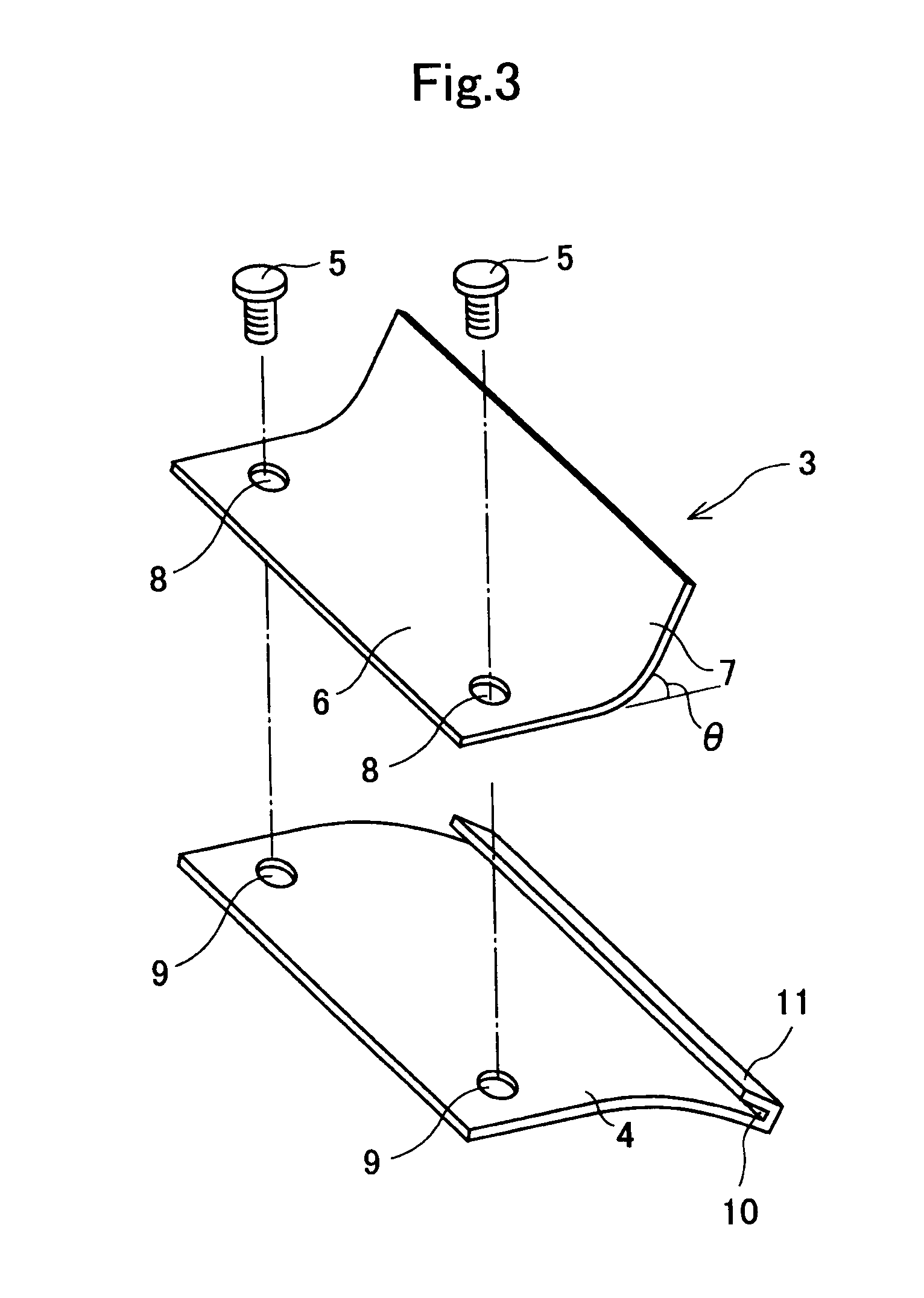
[0145]A smart vortex generator 1 according to the present embodiment mode illustrated in FIG. 1 through FIG. 3 is one which is placed on an aircraft's wing surface, and thereby it is put in service; more concretely, as illustrated in FIG. 4 and FIG. 5, it is placed on a top-surface leading-edge side of an airplane 2's main wing 2a, which possesses a control surface, in a plurality of pieces at intervals in a lateral direction (or in the main wing 2a's longitudinal direc...

embodiment mode 2

[0178]In the same manner as said Embodiment Mode 1, the present embodiment mode shown in FIG. 8 is one which relates to a smart vortex generator demonstrating a bidirectional characteristic by means of a combination of a shape memory alloy's one-way shape memory effect and a bias force comprising a spring force and a fluidic force, and is one in which the blade spring 4's shape is modified in said Embodiment Mode 1.

[0179]Specifically, the blade spring 4 in this embodiment mode is such that, at one of the opposite side ends of the longer side, a clip portion 11 with a cross-sectionally letter-“L” shape, which forms a groove portion into which the leading end of the main body 3's vortex generating portion 7 fits, is formed by means of bending; and additionally is such that, at the other one of the opposite side ends of the longer side, a clip portion 11 with a cross-sectionally letter-“L” shape, which forms a groove portion into which the leading end of the main body 3's base portion ...


PUM

PropertyMeasurementUnit
thicknessaaaaaaaaaa
heightaaaaaaaaaa
heightaaaaaaaaaa

Abstract

A smart vortex generator including a main body, disposed on a body surface, such as a main wing of aircraft, making a boundary to a flow of fluid, and at least a part of which includes a shape memory alloy. A form of the main body, depending on a temperature increment / decrement of the fluid, changes between (1) a first form capable of suppressing a flow separation by a vortex generation and (2) a second form capable of suppressing a turbulent flow, by a phenomenon that the shape memory alloy undergoes a phase transformation between a high-temperature-side stable phase and a low-temperature-side stable phase. The smart vortex generator demonstrates a multi-directional characteristic depending on a temperature change, such that no energy supply from the outside is required. The structure is simple, and repairs and maintenance as well as installation to existing wings are easy.

Description

TECHNICAL FIELD[0001]The present invention relates to a smart vortex generator, which is placed on a body surface making a boundary to a flow of fluid, on a wing surface of aircraft, on a hull surface of vessel or on a surface of wing being installed to the hull, and on a wing surface of rotary machine, and the like, for instance, thereby suppressing a flow separation occurring on the body surface; and an aircraft, a vessel and a rotary machine which are equipped with the same; more particularly, it relates to a smart vortex generator, at least a part of which includes a shape memory alloy or a super-elastic alloy, and which demonstrates a multi-directional characteristic depending on a temperature change of fluid or a change of fluidic force; and an aircraft, a vessel and a rotary machine which are equipped with the same.BACKGROUND ART[0002]A wing of aircraft is designed so that the wing shape becomes optimum upon cruising which takes the longest time in flight routes. Namely, the ...

Claims


Application Information

Patent Timeline
Patent Type & Authority Applications(United States)
IPC IPC(8): B64C23/06
CPCB64C23/06C21D2201/01C21D2211/001C21D2211/008C22C19/03C22F1/006Y02T70/121F05B2240/122F05C2251/08F15D1/12Y02T50/162B63B1/36B63B2231/28F04C2270/20Y02T50/10Y02T70/10
Inventor IKEDA, TADASHIGE
Owner NAGOYA UNIVERSITY
Why Eureka
Try Eureka