
Light-Emitting Element, Light-Emitting Device, Electronic Device and Quinoxaline Derivative

a technology of light-emitting elements and derivatives, which is applied in the direction of organic semiconductor devices, thermoelectric devices, organic chemistry, etc., can solve the problems of difficult to obtain features, short lifetime of light-emitting elements, and poor durability of hole blocking layers, so as to suppress the change over time of carrier balance, the effect of long lifetime and high visibility

Active Publication Date: 2008-09-11
SEMICON ENERGY LAB CO LTD
View PDF11 Cites 24 Cited by
  • Summary
  • Abstract
  • Description
  • Claims
  • Application Information

AI Technical Summary

Benefits of technology

[0011]The present inventors have studied earnestly, and found that a substance having an electron-trapping property is added to an electron-transporting layer to control electron transfer, so that the change over time of carrier balance can be suppressed. Further, we have found that light-emitting elements having long lifetime can be obtained, as a result. Furthermore, we have found that an energy gap of the substance having an electron-trapping property is made larger than an energy gap of a light-emitting substance, so that light emission from the substance having an electron-trapping property can be prevented and the light-emitting element can have excellent color purity.
[0028]By applying a light-emitting element of the present invention to a light-emitting device, the light-emitting device can have long lifetime. Further, by applying a light-emitting element of the present invention to a display portion of an electronic device, the display portion of the electronic device can have long lifetime.

Problems solved by technology

This is a feature which is difficult to be obtained by point light sources typified by an incandescent lamp and an LED or linear light sources typified by a fluorescent lamp.
However, such a hole blocking layer has poor durability as described in Reference 1 and the light-emitting element has short lifetime (Reference 1: Tetsuo Tsutsui and eight others, Japanese Journal of Applied Physics, vol.

Method used


Image

  • Light-Emitting Element, Light-Emitting Device, Electronic Device and Quinoxaline Derivative
  • Light-Emitting Element, Light-Emitting Device, Electronic Device and Quinoxaline Derivative
  • Light-Emitting Element, Light-Emitting Device, Electronic Device and Quinoxaline Derivative

Examples


embodiment modes

[0071]First, a factor of luminance decay in a light-emitting element will now be described. In general, many light-emitting elements are driven by a constant amount of current, and in such a case, luminance decay indicates decrease of current efficiency. The current efficiency is light output with respect to flowing current, and thus is greatly dependent on how many carriers of flowing carriers contribute to recombination (carrier balance) or how many carriers of the carriers recombined (i.e., exciton) in a light-emitting layer contribute to light emission (quantum yield).

[0072]Therefore, as the factor of luminance decay, change over time of carrier balance or deterioration over time of quantum yield is thought to be a major factor. The present invention focuses on change over time of carrier balance.

[0073]Hereinafter, Embodiment Modes will be explained in detail below with reference to the accompanied drawings. It is easily understood by those skilled in the art that modes and deta...

embodiment mode 1

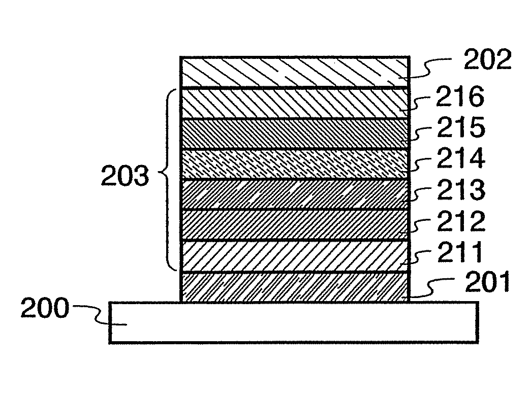
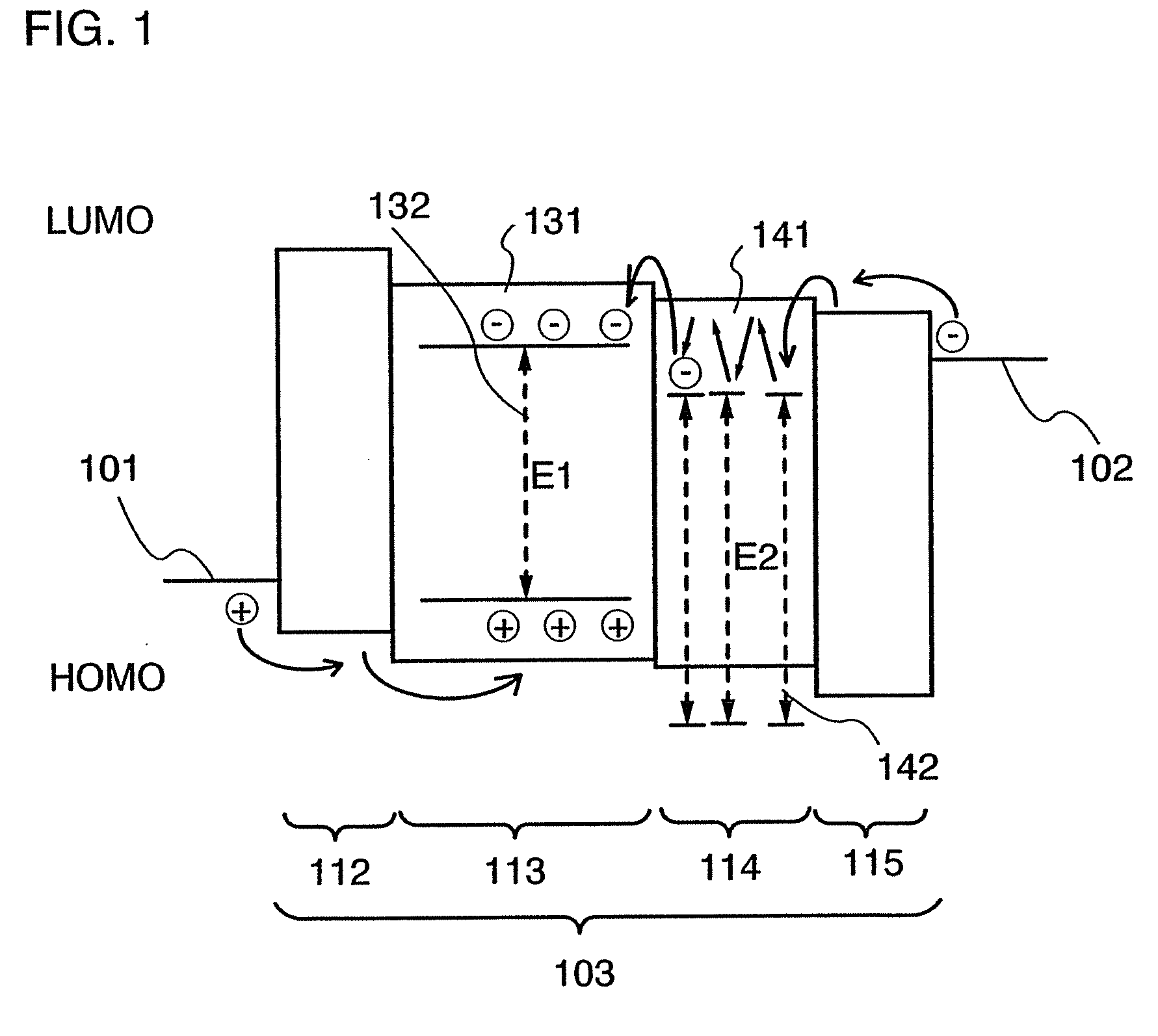
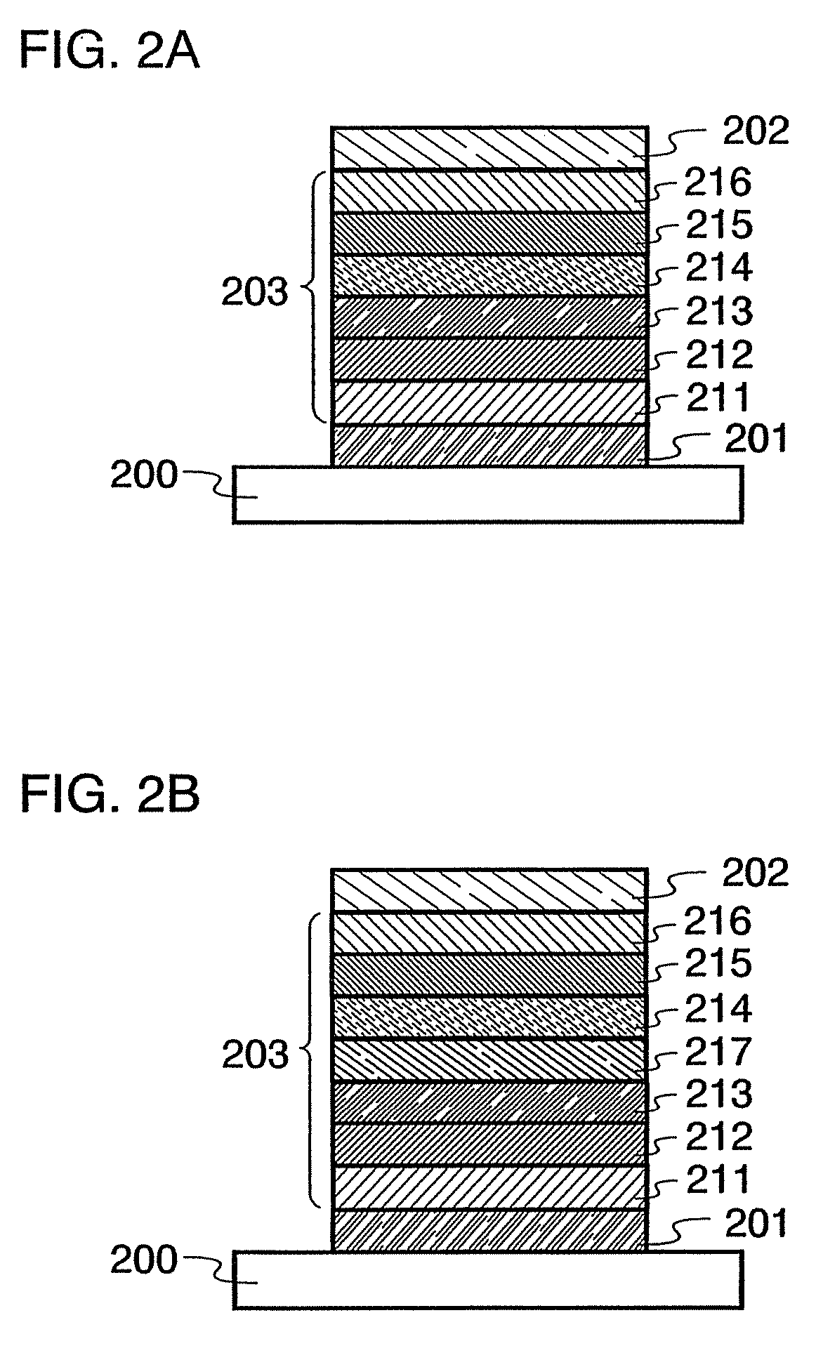
[0075]A principle of a light-emitting element of the present invention will be described first. FIG. 1 is a band diagram of the light-emitting element as an example. The light-emitting element of the present invention includes a first layer 114 and a second layer 113 including a light-emitting substance between a first electrode 101 and a second electrode 102. The first layer 114 is formed between the second layer 113 and the second electrode 102. The first layer 114 includes a first organic compound 141 and a second organic compound 142 each having an electron-transporting property, and includes the first organic compound 141 more than the second organic compound 142. In addition, as shown in FIG. 1, the LUMO level of the second organic compound 142 is lower than the LUMO level of the first organic compound 141, and thus the second organic compound 142 has an electron-trapping property. In addition, the second layer 113 shown in FIG. 1 has a structure in which a light-emitting subs...

embodiment mode 2

[0150]Embodiment Mode 2 will describe a synthesis method of the above quinoxaline derivative of the present invention. A synthesis method is described below, using the quinoxaline derivative represented by the general formula (1) as an example.

[0151]The quinoxaline derivative represented by the general formula (1) can be synthesized from 3,3′-diaminobenzidine, α-diketone A represented by a general formula (3) and α-diketone B represented by a general formula (4).

[0152]Note that at least one of R1 to R10 is any of a fluoro group, a cyano group, a trifluoromethyl group, a nitro group, an acyl group and an acyloxy group, and the others are hydrogen.

[0153]Note that at least one of R11 to R20 is any of a fluoro group, a cyano group, a trifluoromethyl group, a nitro group, an acyl group and an acyloxy group, and the others are hydrogen.

[0154]In other words, as represented in a synthesis scheme (a), 3,3′-diaminobenzidine, α-diketone A represented by the general formula (3) and α-diketone B...


PUM


Abstract

The present invention provides light-emitting element having long lifetime, and light-emitting devices and electronic devices having long lifetime. A light-emitting element comprises a first layer and a second layer including a light-emitting substance between a first electrode and a second electrode. The first layer includes a first organic compound and a second organic compound, the first layer is formed between the second layer and the second electrode, the first layer includes the first organic compound more than the second organic compound, the first organic compound is an organic compound having an electron-transporting property, the second organic compound is an organic compound having an electron-trapping property, an energy gap of the second organic compound is larger than that of the light-emitting substance; and a voltage is applied such that a potential of the first electrode is higher than that of the second electrode, so that the light-emitting layer emits light.

Description

TECHNICAL FIELD[0001]The present invention relates to current excitation type light-emitting elements. Further, the present invention relates to light-emitting devices and electronic devices having the light-emitting element.BACKGROUND ART[0002]In recent years, research and development have been actively conducted on light-emitting elements using electroluminescence. In a basic structure of such a light-emitting element, a layer including a substance having a light-emitting property is interposed between a pair of electrodes. By voltage application to this element, light emission can be obtained from the substance having a light-emitting property.[0003]Since such light-emitting elements is of self-light-emitting type, it is considered that the light-emitting elements have advantages over liquid crystal display devices in that visibility of pixels is high, backlight is not required, and so on and is therefore suitable as flat panel display elements. In addition, other advantages of s...

Claims


Application Information

Patent Timeline
IPC IPC(8): H01L51/46
CPCC07D241/42C09K11/06C09K2211/1007C09K2211/1011H05B33/14H01L51/0072H01L51/0081H01L51/5048H01L2251/552C09K2211/1044H10K85/324H10K85/6572H10K50/14H10K2101/30H10K85/615
Inventor SUZUKI, TSUNENORISEO, SATOSHIKAWAKAMI, SACHIKO
Owner SEMICON ENERGY LAB CO LTD
Learn More