Low power flip-flop circuit

a flip-flop circuit and low power technology, applied in the field of sequential digital circuits, can solve the problems of high switching current during dynamic transition, high power dissipation, imperfect rise at the node cp, etc., to prevent false edge generation, prevent power dissipation in the flip-flop circuit, and reduce the effect of switching curren

Inactive Publication Date: 2008-09-11
STMICROELECTRONICS PVT LTD
View PDF5 Cites 36 Cited by
  • Summary
  • Abstract
  • Description
  • Claims
  • Application Information

AI Technical Summary

Benefits of technology

[0013]Another embodiment provides a method for providing low power dissipation in a flip-flop circuit. The method may comprise receiving an input signal through an input node of the flip-flop circuit and comparing the input signal with an output signal for providing a comparison signal through a sensing circuit. Additionally, the method may inclu

Problems solved by technology

Also, in digital designs, comprising millions of flip-flops and clock tree buffers, there is a high amount of switching current during dynamic transitions.
This results in high power dissipation and an imperfect rise at the node CP.
Since the CP signal drives the master and slave of the flip-flop circuit, the poor nature of the signal degrades the delay, the setup time, the hold time, and the power dissipation associated with the flip-flop

Method used


Image

  • Low power flip-flop circuit
  • Low power flip-flop circuit
  • Low power flip-flop circuit

Examples


Embodiment Construction

[0028]The preferred embodiments of the present invention will be described in detail with reference to the accompanying drawings. However, the present invention is not limited to the preferred embodiments. The present invention can be modified in various forms. The preferred embodiments of the present invention are only provided to explain more clearly the present invention to one of ordinary skill in the art of the present invention. In the accompanying drawings, like reference numerals are used to indicate like components.

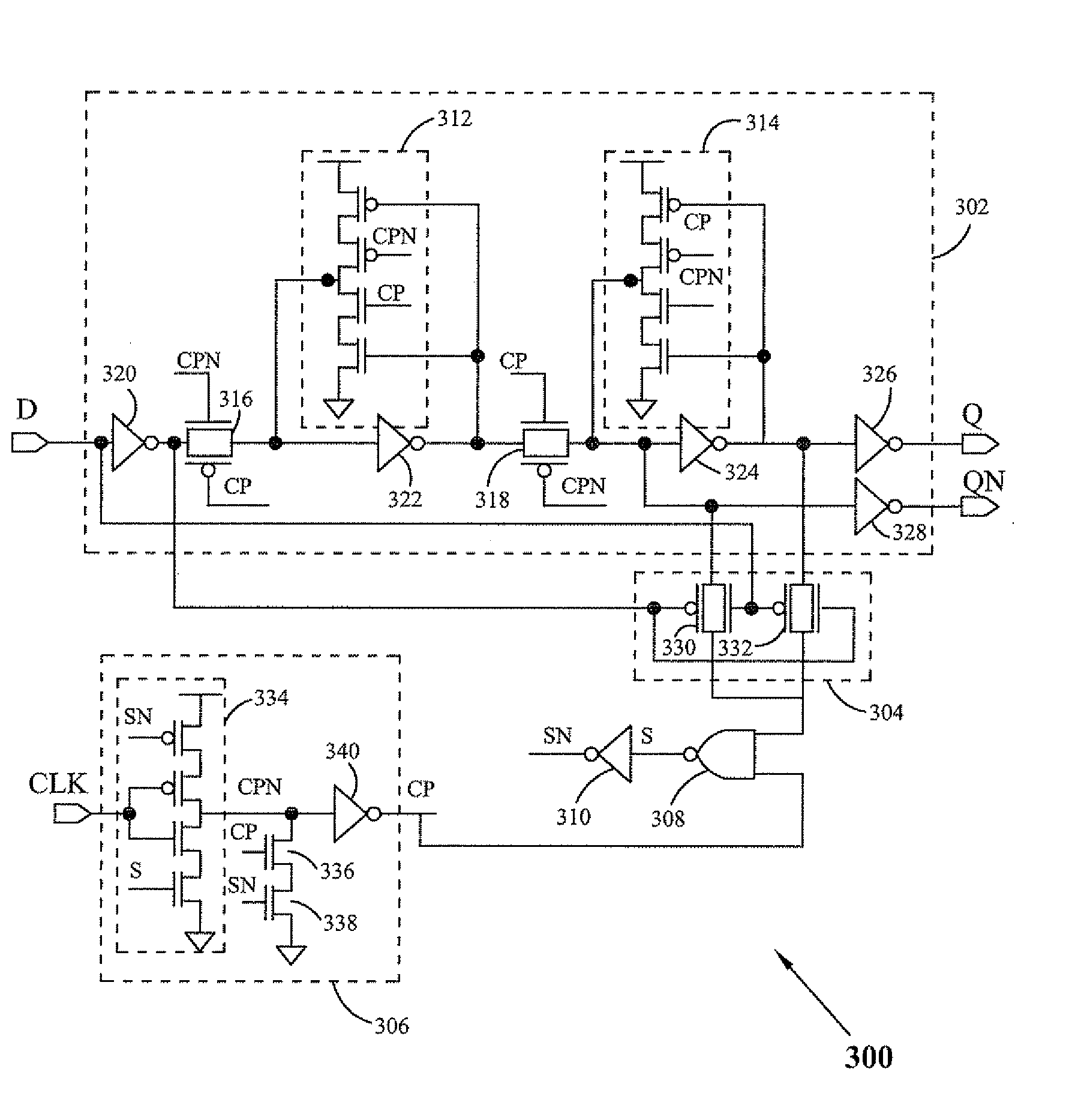
[0029]FIG. 3 illustrates a flip-flop circuit 300 according to an embodiment of the present invention. The flip-flop 300 utilizes low power and thus can be used for low electromagnetic interference (EMI) applications. The circuit 300 includes a flip-flop circuit 302, a sensing circuit 304, a clock generating circuit 306, a NAND gate 308 and an inverter 310. The flip-flop circuit 302 includes two tri-state inverters 312 and 314, two transmission gates 316 and 318 a...


PUM


Abstract

A flip-flop circuit having low power consumption includes a sensing circuit, and a clock generating circuit. The flip-flop is leading edge triggered and operates on an internally generated pseudo clock signal. The sensing circuit senses a change in an input signal and an output signal of the flip-flop. The clock generating circuit generates a pseudo clock signal with a sharp rise and fall based upon an external clock signal.

Description

FIELD OF THE INVENTION[0001]The present invention relates to sequential digital circuits and more specifically to a low power flip-flop circuit, which can be utilized in low electromagnetic interference applications.BACKGROUND OF THE INVENTION[0002]In various digital circuits, flip-flops are the fundamental sequential logic element. Power dissipated or consumed in the flip-flops makes up a significant portion of the total power dissipation in a circuit design. Thus, by reducing power dissipation in the flip-flops, the performance of the design can be improved drastically. Also, in digital designs, comprising millions of flip-flops and clock tree buffers, there is a high amount of switching current during dynamic transitions. The current in clock tree buffers cannot be controlled, but we can lower the switching current in the flip-flops to lower the electromagnetic emissions.[0003]FIG. 1 illustrates a conventional flip-flop circuit 100. The flip-flop circuit 100 includes a master lat...

Claims


Application Information

Patent Timeline
IPC IPC(8): H03K3/289
CPCH03K3/012H03K19/0013H03K3/356156
Inventor JAIN, ABHISHEK
Owner STMICROELECTRONICS PVT LTD
Why Eureka
Try Eureka