High Frequency Electromagnetic Wave Receiver and Broadband Waveguide Mixer

a technology of electromagnetic waves and mixers, applied in the direction of waveguides, electromagnetic wave demodulation, electrical devices, etc., can solve the problems of low noise and low cost of conventional solutions, inability to solve the problem of broadband reception with low noise and low cost, and the size of rectangular waveguides, which can operate in single mode within the millimeter wave band, etc., to achieve low loss, high frequency (hf), and broad single mode operating frequency band

Inactive Publication Date: 2008-09-11
NXP BV
View PDF10 Cites 5 Cited by
  • Summary
  • Abstract
  • Description
  • Claims
  • Application Information

AI Technical Summary

Benefits of technology

[0010]The technical problem to be solved by the present invention is how to make a mixer operating in the millimeter wave band having good broadband performances as well as lower heat noise and is easier to be produced and assembled.
[0013]Since the present invention adopts the V-groove waveguide architecture, which is suitable for the transmission of millimeter waves and sub-millimeter waves, the broadband waveguide mixer and the high frequency (HF) electromagnetic wave receiver of the present invention have the advantages of broad single mode operating frequency band, lower loss, low noise and easy production and assembling. In addition, because of the broadband receiving functionality supported by the bowtie dipole antenna, which belongs to broadband antennas, the broadband waveguide mixer and HF electromagnetic wave receiver of the present invention can normally operate in a broader frequency range.

Problems solved by technology

However, the conventional solutions cannot solve the problem of broadband reception with low noise and low cost due to their disadvantages of high cost, non-trivial structural loss, multi-mode interference, etc.
In particular, the size of the rectangular waveguide, which can operate in single mode within the millimeter wave band, is very small.
Therefore, it makes processing and assembling difficult and increases the production costs.
Although oversized rectangular guides can be adopted to solve the size problem, the multi-mode interference induced by the oversized rectangular guides is disadvantageous to the design of broadband mixers.
On the other hand, because of the skin effect, the transmission loss of rectangular waveguides operating in the millimeter wave band is extremely high, which is also disadvantageous to lower the noise of the mixers.
The patches surely increase the dielectric losses during the transmission of millimeter wave signals.
Especially, when the operating frequency is over 100 GHz, the losses become extremely severe.
Secondly, serious parasitic parameter interference also limits the highest operating frequency of integrated circuits mixers.
Thus, the existing integrated circuit type is not suitable for implementing mixers operating in the millimeter wave band.
Such kind of mixers is structurally complicated and oversized and requires optical alignment.
Thus, it will increase the processing difficulty of the mixers and the costs of production.
In summary, using the present technologies cannot provide a mixer, which can operate in the millimeter wave band, provide good broadband performance as well as lower heat noise and are easily produced and assembled.

Method used


Image

  • High Frequency Electromagnetic Wave Receiver and Broadband Waveguide Mixer
  • High Frequency Electromagnetic Wave Receiver and Broadband Waveguide Mixer
  • High Frequency Electromagnetic Wave Receiver and Broadband Waveguide Mixer

Examples


Embodiment Construction

[0023]In the following, the embodiments of the present invention will be described in details with reference to the attached figures.

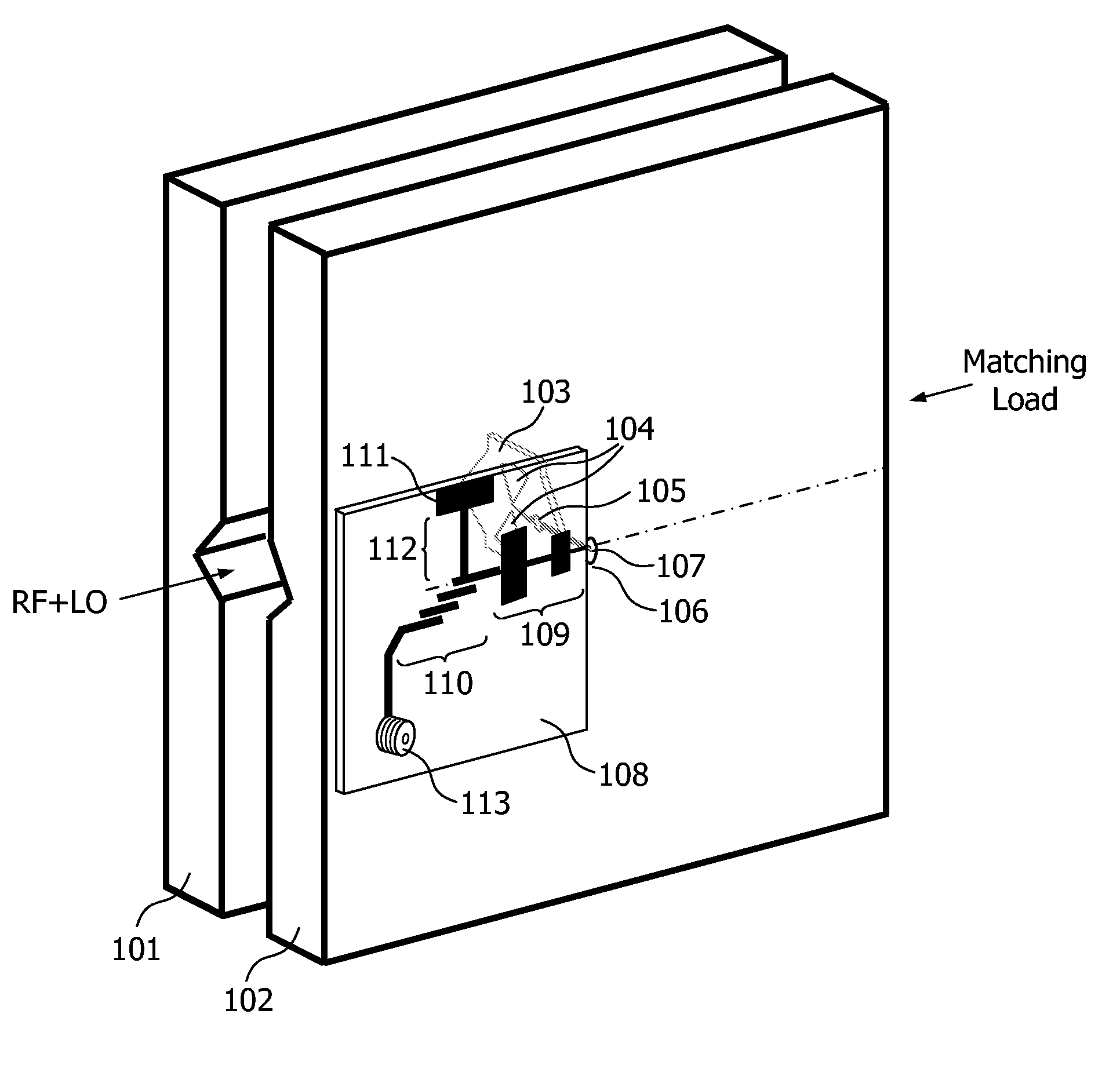
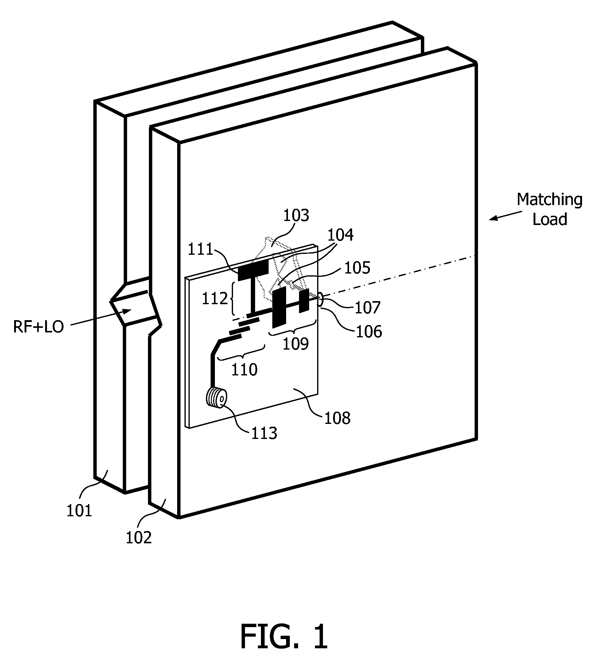
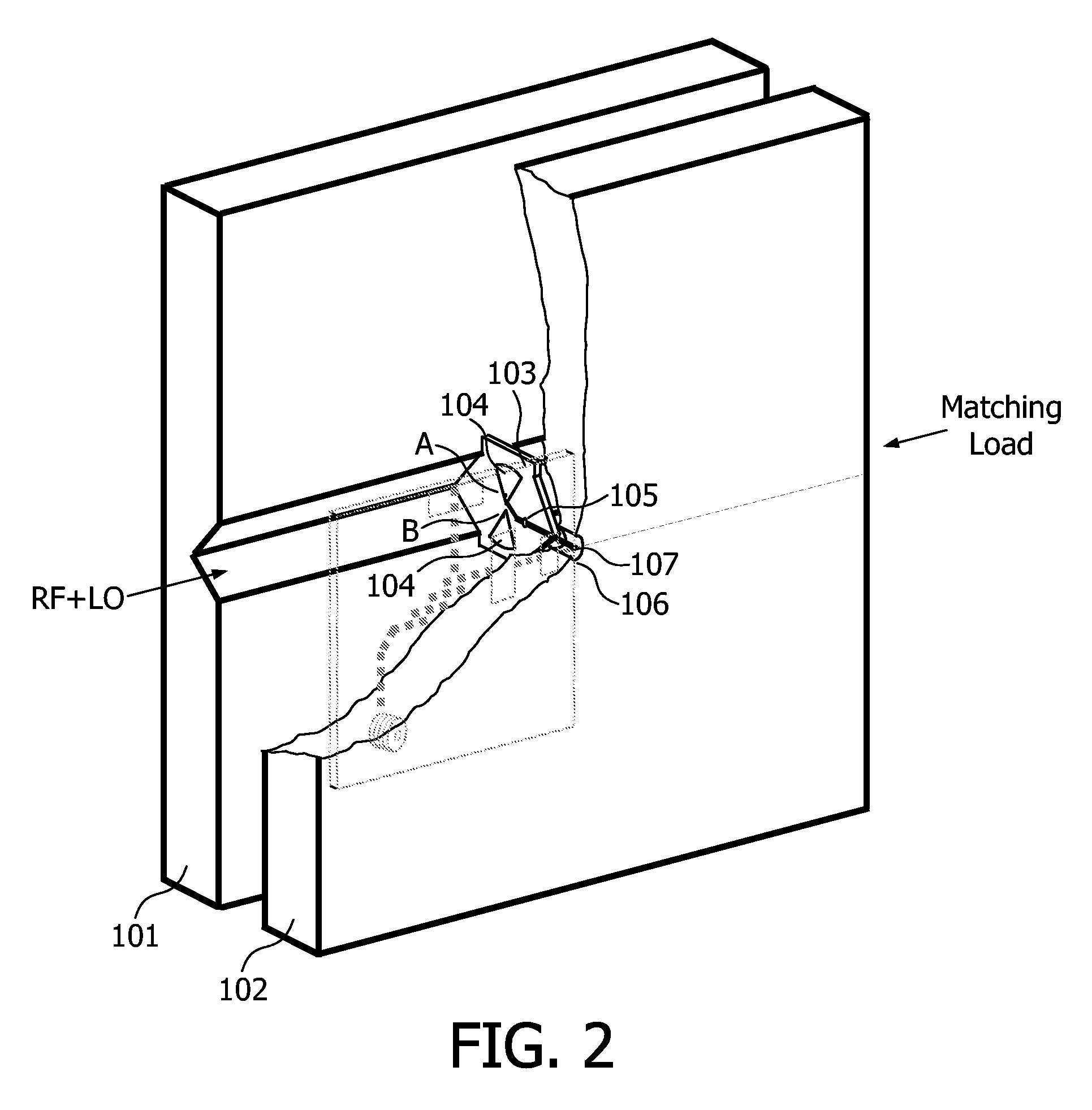
[0024]FIG. 1 is a view showing the external structure of a V-groove waveguide mixer of an embodiment of the present invention. In FIG. 1, numeral 101 and numeral 102 represent two metal plates with V-groove; numeral 103 represents an HF dielectric patch, numeral 104 represents a bowtie dipole antenna, numeral 105 represents a diode; numeral 106 represents a hole on the metal plate 102, whose inner surface has metal properties; numeral 107 represents a conductor, which is in the hole 106 and connects the diode 105 with one of its ends; numeral 108 represents a dielectric patch, on which a planar circuit is formed; numerals 109, 110, 111, 112 respectively represent an impedance conversion element, a filter element, a metal plate element and an intermediate frequency (IF) transmission line; numeral 113 represents a coaxial connector. Connections and funct...


PUM


Abstract

The present invention provides a broadband waveguide mixer, comprising: a waveguide having a substantially v-shaped groove in its inner surface; a broadband antenna coupling in the V-groove; and mixing means for mixing signals received by the broadband antenna. The present invention further provides a high frequency electromagnetic wave receiver comprising the aforesaid broadband waveguide mixer. The broadband waveguide mixer and the high frequency electromagnetic wave receiver have the advantages of broad single mode operating frequency band, lower loss, lower noise, and they can be easily produced and assembled to lower cost.

Description

FIELD OF THE INVENTION[0001]1. Field of the Invention[0002]The present invention relates to a high frequency electromagnetic wave receiver, more particularly to a broadband waveguide mixer.[0003]2. Background of the Invention[0004]With the development of millimeter wave (30 GHz-300 GHz) and sub-millimeter wave (300 GHz-3 THz) technologies, the above frequency bands are highly possible to be applied to personal wireless broadband communication and indoor multi-media wireless access technologies. Additionally, since the atmosphere attenuation and reverse dispersion of millimeter wave are smaller than those of infrared, the band of millimeter wave is suitable for transmission and communication in atrocious weather situations (e.g., in the existence of suspended particulates like fume and dust) and therefore it can also be used as communication means for some complicated environments, such as automobile electronics and traffic navigation. Accordingly, broadband mixers, which have broad ...

Claims


Application Information

Patent Timeline
Patent Type & Authority Applications(United States)
IPC IPC(8): H01P3/00H01P5/12
CPCH01P1/005H03D9/0641H01P3/123
Inventor LIU, YONGYUAN, YUN
Owner NXP BV
Why Eureka
Try Eureka