

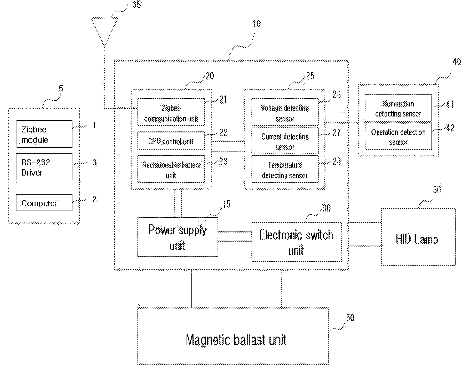
Ballast control system for hid lamp using zigbee
a technology of magnetic ballast control and hid lamp, which is applied in the direction of audible advertising, instruments, high-level techniques, etc., can solve the problems of difficult control of illumination, low failure rate, and high manufacturing cost, and achieve the effect of easy confirmation of the time for replacing the hid lamp
- Summary
- Abstract
- Description
- Claims
- Application Information
AI Technical Summary
Benefits of technology
Problems solved by technology
Method used
Image

Examples
embodiment 1
Control of a Constant Power Type Magnetic Ballast for a HID Lamp
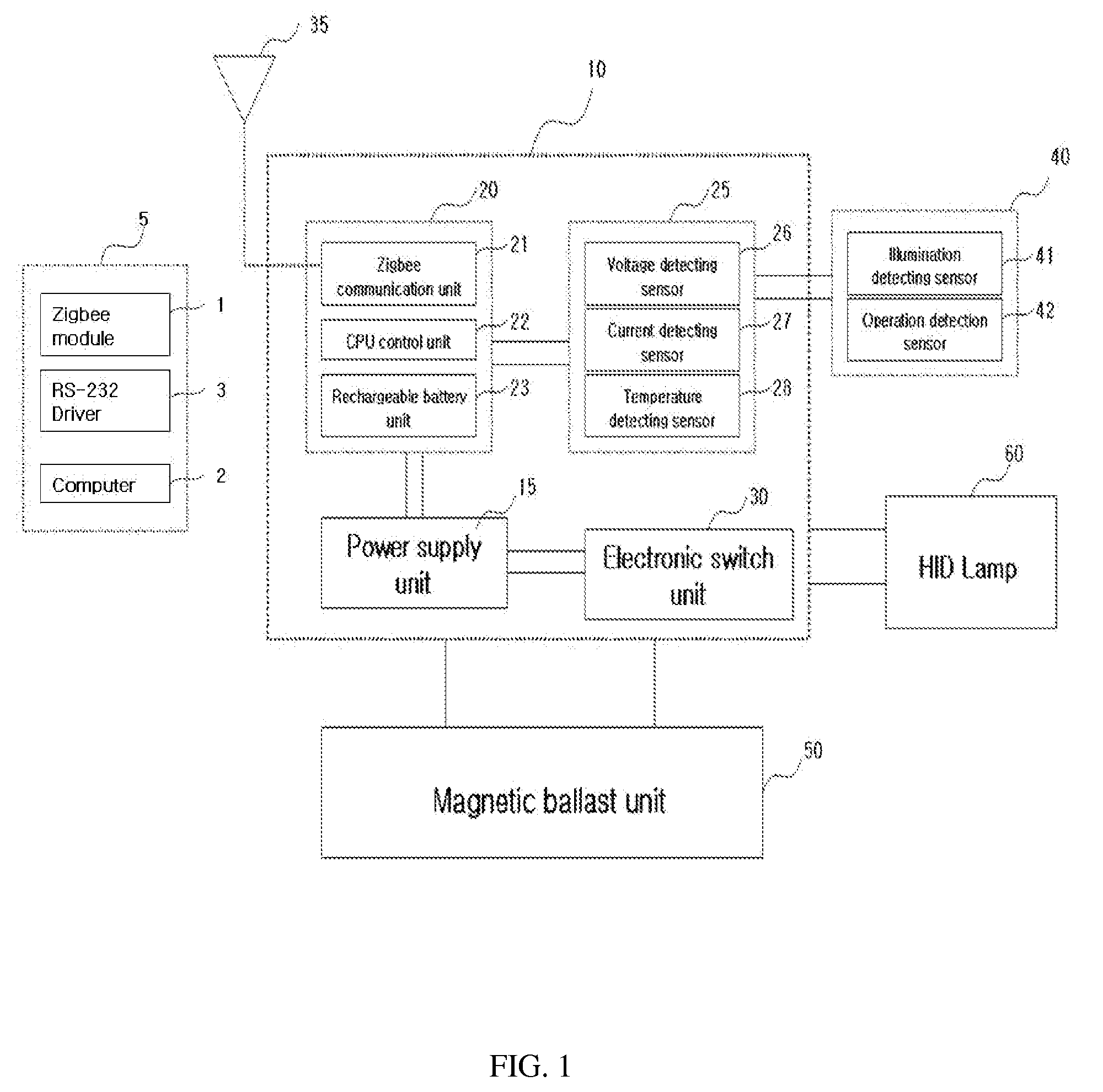
[0056]When the value of the power factor improving condenser is 15 uF and outputted 100%, combination steps of the condensers are shown below.
[0057]1-1: Two step illumination control
[0058]Two power factor improving condensers having values of 10 uF and 5 uF respectively were combined.
TABLE 1Categories10 uF5 uFTotalTurn onusedused10 uF + 5 uF = 15 uF (output 100%)controlusedunusedOnly use 10 uF = 10 uF (output 50%)illuminationTurn offunusedunusedPower off (output 0%)
[0059]1-2: Four Step Illumination Control
[0060]Three power factor improving condensers having values of 10 uF, 3 uF, and 2 uF respectively were combined.
TABLE 2Categories10 uF3 uF2 uFTotalTurn onusedusedused10 uF + 3 uF + 2 uF = 15 uF(output 100%)Controlusedusedunused10 uF + 3 uF = 13 uFillumination(output 80%)Controlusedunusedused10 uF + 2 uF = 15 uFillumination(output 70%)Controlusedunusedunusedonly use 10 uF = 10 uFillumination(output 50%)Turn offunusedunu...
embodiment 2
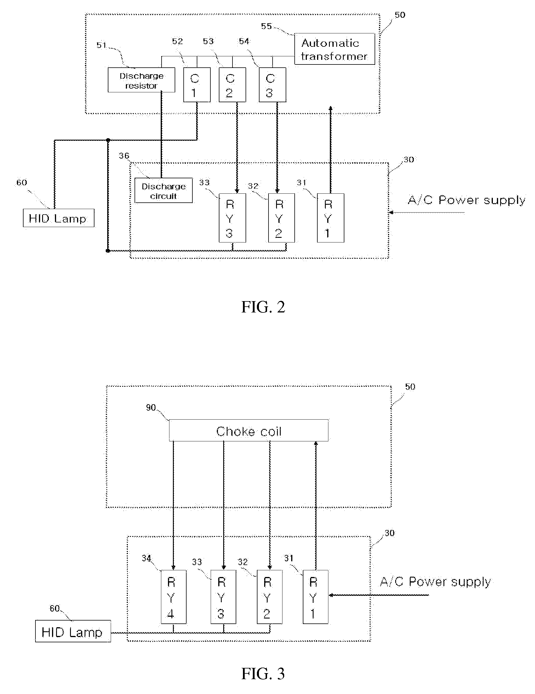
Control of a Choke Coil Type Magnetic Ballast for a HID Lamp
[0063]Illumination control of the choke coil type magnetic ballast for a HID lamp was accomplished as shown in FIG. 4. In the circuit of a general-purpose choke coil type magnetic ballast for a HID lamp, a basic CCP (a choke coil+capacitor for improving a power factor+an igniter) is configured to connect output lines to an intermediate portion of the choke coil, and illumination of the HID lamp was controlled by adjusting the output capacity of the choke coil.
[0064]FIG. 5 is a view showing the circuit diagram of a choke coil type magnetic ballast with an embedded igniter according to the present invention, in which a HID lamp of 400 Watts was used. Illumination of the lamp was controllable as high as 300 Watts, and an output line of 350 Watts which is an intermediate value between the 400 Watts and the 300 Watts is connected, thereby constructing a three-step illumination control system.
[0065]Illumination control of the cho...
PUM
 Abstract
Description
Claims
Application Information