Membrane electrode assembly, method for manufacturing the same, and fuel cell including the same

a technology of membrane electrodes and fuel cells, applied in the field of fuel cells, can solve the problems of lowering power generation efficiency and hindering the catalyst layer, and achieve the effect of preventing the drop in power generation efficiency

Inactive Publication Date: 2008-09-11
JX NIPPON OIL & ENERGY CORP
View PDF1 Cites 11 Cited by
  • Summary
  • Abstract
  • Description
  • Claims
  • Application Information

AI Technical Summary

Benefits of technology

[0010]The present invention has been made in view of the foregoing circumstances, and a general purpose thereof is to provide a technology capable of preventing drop in power generation efficiency due to water produced at the cathode.

Problems solved by technology

As described above, water is produced at the cathode, and thus if the water stays on the cathode, the diffusion of air to the catalyst layer can be hindered, which can lead to lowered power generation efficiency.

Method used


Image

  • Membrane electrode assembly, method for manufacturing the same, and fuel cell including the same
  • Membrane electrode assembly, method for manufacturing the same, and fuel cell including the same
  • Membrane electrode assembly, method for manufacturing the same, and fuel cell including the same

Examples


first embodiment

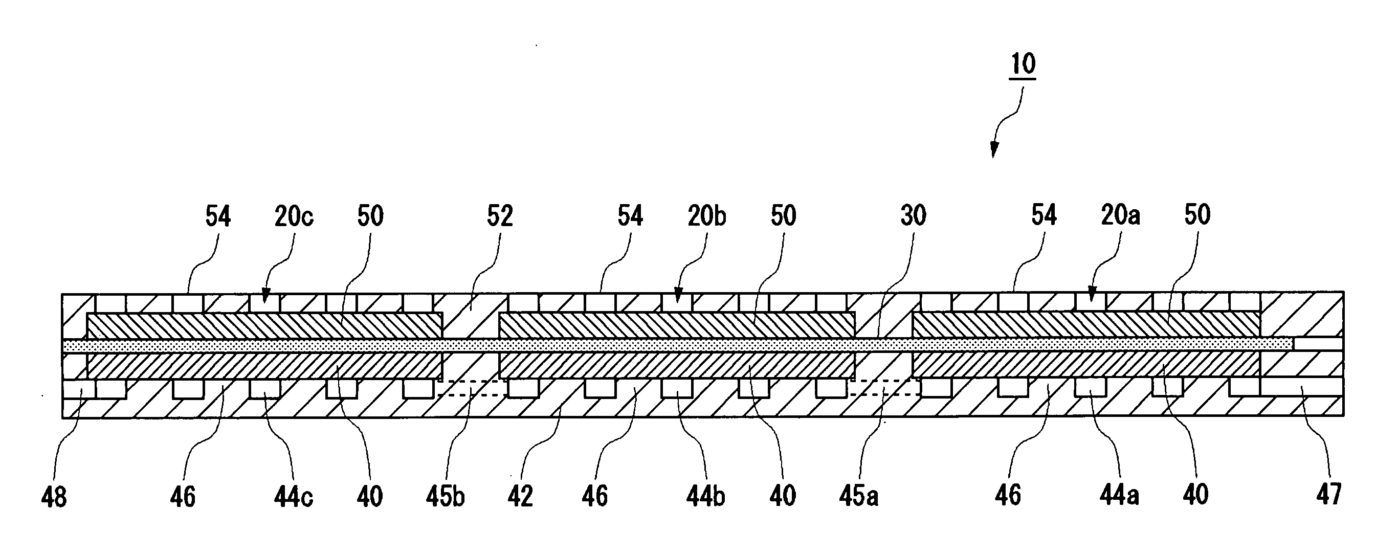
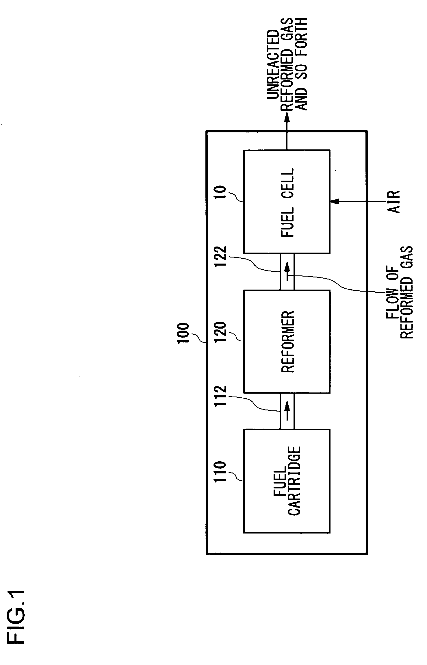
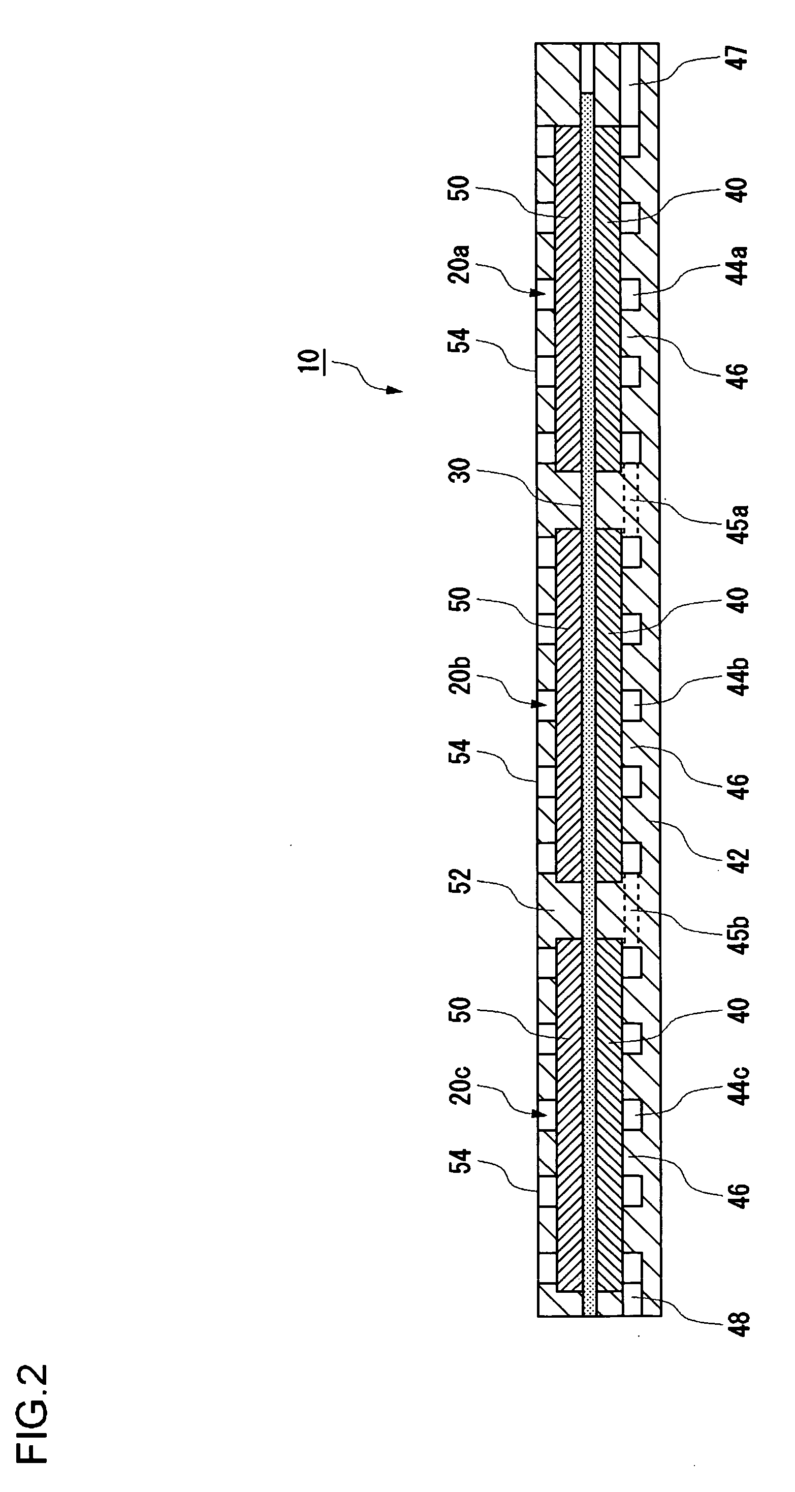
[0042]FIG. 1 is a schematic diagram showing a structure of a fuel cell system 100 according to a first embodiment of the present invention. The fuel cell system 100 according to the first embodiment can be suitably used as a power source for mobile devices such as notebook-sized PCs or mobile phones. As illustrated in FIG. 1, the fuel cell system 100 includes a fuel cartridge 110, a reformer 120, and a fuel cell 10.

[0043]The fuel cartridge 110 stores a hydrocarbon fuel, such as methanol, methane or butane. The fuel cartridge 110 is detachable, so that when the hydrocarbon fuel has been mostly consumed, the one with little remaining content may be replaced with a new one charged sufficiently with the hydrocarbon fuel. The hydrocarbon fuel discharged from the fuel cartridge 110 is sent to the reformer 120 via piping 112. Note that there may be a carburetor, a desulfurizer, or such other arrangement installed between the fuel cartridge 110 and the reformer 120 as required.

[0044]The ref...

second embodiment

[0069]FIG. 4 is a top view of a membrane electrode assembly according to a second embodiment of the present invention. The membrane electrode assembly 160 according to the second embodiment has discontinuously and linearly arranged grooves 168 surrounded by an electrode-forming region Y unlike the linear grooves 68 of the membrane electrode assembly 60 according to the first embodiment. This arrangement improves the strength of the membrane electrode assembly 160.

third embodiment

[0070]FIG. 5 is a top view of a membrane electrode assembly according to a third embodiment of the present invention. The membrane electrode assembly 260 according to the third embodiment has continuous and zigzag-like bent grooves 268 surrounded by an electrode-forming region Y unlike the linear grooves 68 of the membrane electrode assembly 60 according to the first embodiment. This arrangement improves the strength of the membrane electrode assembly 260.


PUM

PropertyMeasurementUnit
widthaaaaaaaaaa
thicknessaaaaaaaaaa
oscillation wavelengthaaaaaaaaaa

Abstract

A membrane electrode assembly includes an electrolyte membrane, an anode disposed on one face of the electrolyte membrane, and a cathode disposed on the other face of the electrolyte membrane. The electrolyte membrane has a non-electrode-forming region where the cathode is not disposed on the surface of the non-electrode-forming region and an electrode-forming region where the cathode is disposed on the surface of the electrode-forming region. The non-electrode-forming region has a thin membrane region where the membrane is thinner than that in the electrode-forming region. The drop in power generation efficiency by water generated at the cathodes is prevented.

Description

CROSS-REFERENCE TO RELATED APPLICATIONS[0001]This application is based upon and claims the benefit of priority from the prior Japanese Patent Application No. 2007-060911, filed on Mar. 9, 2007, and Japanese Patent Application No. 2008-025700, filed on Feb. 5, 2008, the entire contents of which are incorporated herein by reference.BACKGROUND OF THE INVENTION[0002]1. Field of the Invention[0003]The present invention relates to a fuel cell for generating electrical energy by the use of a fuel containing hydrogen.[0004]2. Description of the Related Art[0005]Recently much attention has been focused on fuel cells that feature not only high energy conversion efficiency but also no hazardous substance produced by the electricity-generating reaction. Known as one of such fuel cells is the polymer electrolyte fuel cell which operates at temperatures below 100° C.[0006]A polymer electrolyte fuel cell, which has a basic structure of a solid polymer electrolyte membrane disposed between a fuel e...

Claims


Application Information

Patent Timeline
Patent Type & Authority Applications(United States)
IPC IPC(8): H01M8/10H01M8/00
CPCH01M8/1004Y10T29/49108Y02E60/521H01M8/241H01M8/2418Y02E60/50Y02P70/50
Inventor FUKUSHIMA, MAKOTOYASUO, TAKASHIIMURA, SHINICHIRO
Owner JX NIPPON OIL & ENERGY CORP
Why Eureka
Try Eureka