Antenna

a broadband antenna and antenna technology, applied in the direction of loop antennas, resonant antennas, radiating element structural forms, etc., can solve the problem of insufficient broad band width

Active Publication Date: 2008-09-18
MURATA MFG CO LTD
View PDF81 Cites 8 Cited by
  • Summary
  • Abstract
  • Description
  • Claims
  • Application Information

AI Technical Summary

Benefits of technology

[0006]To overcome the problems described above, preferred embodiments of the present invention provide a small antenna in which a broad band is achieved.
[0012]Moreover, the inductance elements included in the plurality of resonant circuits may be defined by a line electrode pattern in which the inductance elements are disposed in the direction of one axis. It is preferable that the capacitance elements be electrically connected to the power supply terminals for surge protection. When the capacitance elements are provided in a laminated substrate, reduction in the size is not inhibited. When the plurality of resonant circuits is provided in a laminated substrate, a reduction in the size is further facilitated, and the manufacturing is also facilitated by a lamination method.
[0014]In the antenna according to the third preferred embodiment, the first and second LC series resonant circuits are used to radiate radio waves, and the first and second inductance elements function as inductances of a matching circuit, such that the impedance of devices connected to the first and second power supply terminals and the impedance (approximately 377Ω) of space can be matched in a substantially broad band. Moreover, the individual elements can be readily constructed in a laminate. Thus, a small surface-mountable broadband antenna is obtained.

Problems solved by technology

Moreover, although the band width of each frequency band is broad as compared to that of a helical antenna including a single coil, a sufficiently broad band width cannot be achieved.

Method used


Image

  • Antenna
  • Antenna
  • Antenna

Examples


first preferred embodiment

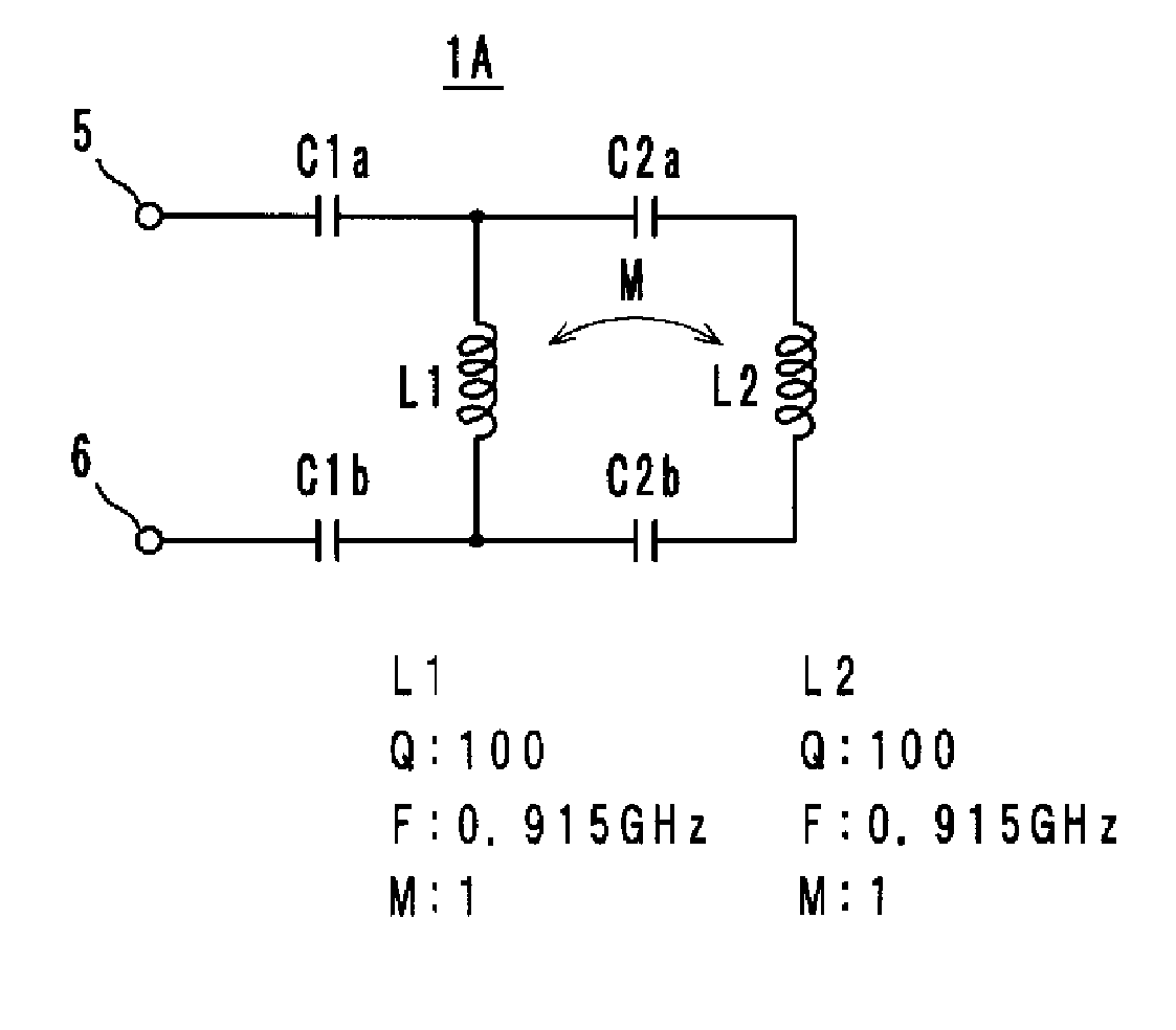
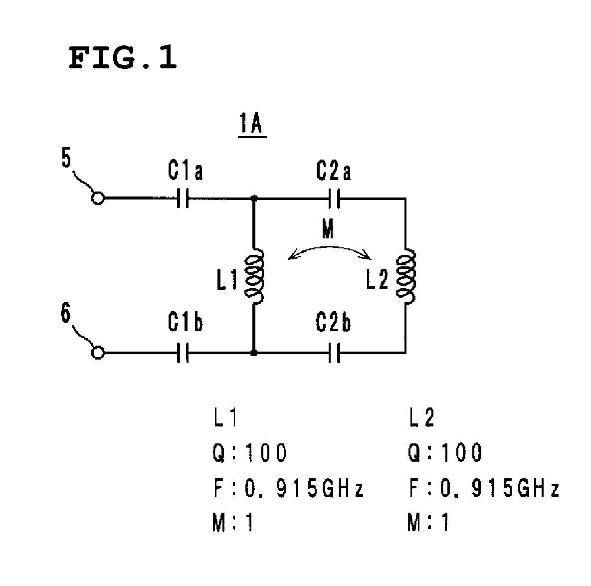
[0050]An antenna 1A according to a first preferred embodiment includes inductance elements L1 and L2 that have different inductance values and are magnetically coupled together in phase (indicated by a mutual inductance M), as shown as an equivalent circuit in FIG. 1. The inductance element L1 is connected to power supply terminals 5 and 6 via capacitance elements C1a and C1b, and is connected in parallel with the inductance element L2 via capacitance elements C2a and C2b. That is to say, this resonant circuit includes an LC series resonant circuit that includes the inductance element L1 and the capacitance elements C1a and C1b and an LC series resonant circuit that includes the inductance element L2 and the capacitance elements C2a and C2b.

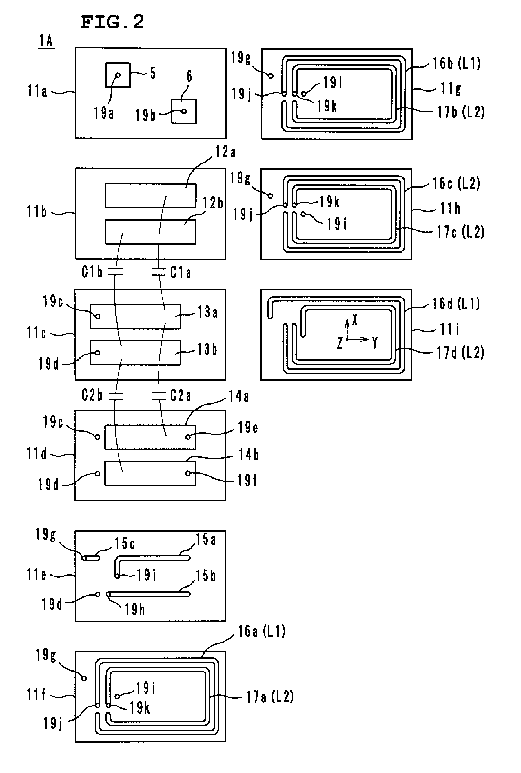
[0051]The antenna 1A having the aforementioned circuit configuration is defined by a laminate shown as an example in FIG. 2, and includes ceramic sheets 11a to 11i of dielectric material that are laminated, pressure bonded, and fired together. T...

second preferred embodiment

[0061]An antenna 1B according to a second preferred embodiment includes the inductance elements L1 and L2, which have different inductance values and are magnetically coupled together in phase (indicated by the mutual inductance M), as shown as an equivalent circuit in FIG. 7. One end of the inductance element L1 is connected to the power supply terminal 5 via a capacitance element C1, and is connected to the inductance element L2 via a capacitance element C2. Moreover, the other ends of the inductance elements L1 and L2 are connected directly to the power supply terminal 6. That is to say, this resonant circuit includes an LC series resonant circuit that includes the inductance element L1 and the capacitance element C1 and an LC series resonant circuit that includes the inductance element L2 and the capacitance element C2, and is substantially the same as the antenna 1A according to the first preferred embodiment, the capacitance elements C1b and C2b being omitted from the antenna ...

third preferred embodiment

[0070]An antenna 1C according to a third preferred embodiment includes blocks A, B, and C, each of which includes two LC series resonant circuits, as shown as an equivalent circuit in FIG. 11. The LC series resonant circuits included in each of the blocks A, B, and C have the same circuit configuration as the antenna 1A according to the first preferred embodiment, and the detailed description is omitted.

[0071]In the antenna 1C, laminates, each shown in FIG. 2, are disposed in parallel as the blocks A, B, and C, and the LC series resonant circuits in each of the blocks A, B, and C are connected to the common power supply terminals 5 and 6, as shown in FIG. 12.

[0072]In the antenna 1C having the aforementioned structure, the LC series resonant circuits, which respectively include the inductance elements L1 and L2, inductance elements L3 and L4, and inductance elements L5 and L6, magnetically coupled together, resonate and function as a radiating element. Moreover, the inductance elemen...


PUM


Abstract

An antenna includes inductance elements that are magnetically coupled together, an LC series resonant circuit that includes one of the inductance elements and capacitance elements, and an LC series resonant circuit that includes another of the inductance elements and capacitance elements. The plurality of LC series resonant circuits are used to radiate radio waves and are used as inductances of a matching circuit that matches an impedance when a power supply side is viewed from power supply terminals and a radiation impedance of free space.

Description

BACKGROUND OF THE INVENTION[0001]1. Field of the Invention[0002]The present invention relates to antennas, and in particular, to a small surface-mountable broadband antenna.[0003]2. Description of the Related Art[0004]A helical antenna is disclosed in Japanese Unexamined Patent Application Publication No. 2003-37426 (Patent Document 1) as a small antenna that is used in mobile communication, such as cellular phones. The helical antenna enables operation in two frequency bands by winding an excitation coil around a long and narrow insulating main body in a helical fashion and winding first and second non-feeding coils around the main body in a helical fashion so that the first and second non-feeding coils are located adjacent to the excitation coil.[0005]However, the spacing between the two frequency bands, in which the helical antenna can operate, is equal to or greater than several hundreds of megahertz, and the two frequency bands cannot be set close to each other so that the spac...

Claims


Application Information

Patent Timeline
Patent Type & Authority Applications(United States)
IPC IPC(8): H01Q9/00H01Q1/50H01Q1/38H01Q5/10H01Q7/00
CPCH01Q1/243H01Q1/38H01Q1/50H01Q5/40H01Q9/27H01Q5/321H01Q5/371H01Q7/00
Inventor KATO, NOBORU
Owner MURATA MFG CO LTD
Why Eureka
Try Eureka