Crankshaft, internal combustion engine, transportation apparatus, and production method for crankshaft
- Summary
- Abstract
- Description
- Claims
- Application Information
AI Technical Summary
Benefits of technology
Problems solved by technology
Method used
Image
Examples
Embodiment Construction
[0051]Hereinafter, preferred embodiments of the present invention will be described with reference to the accompanying drawings. Note that the present invention is not limited to the following preferred embodiments.
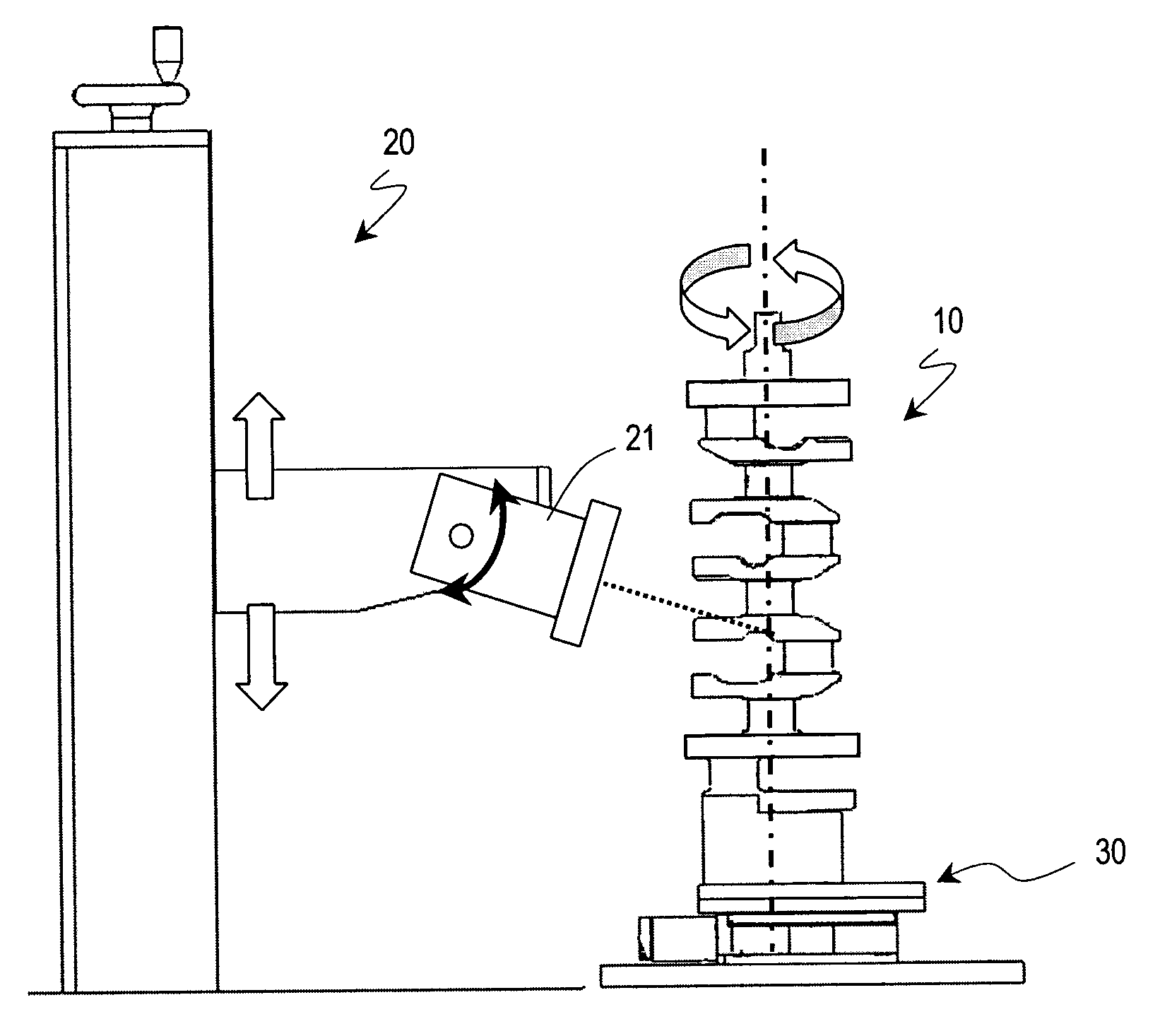
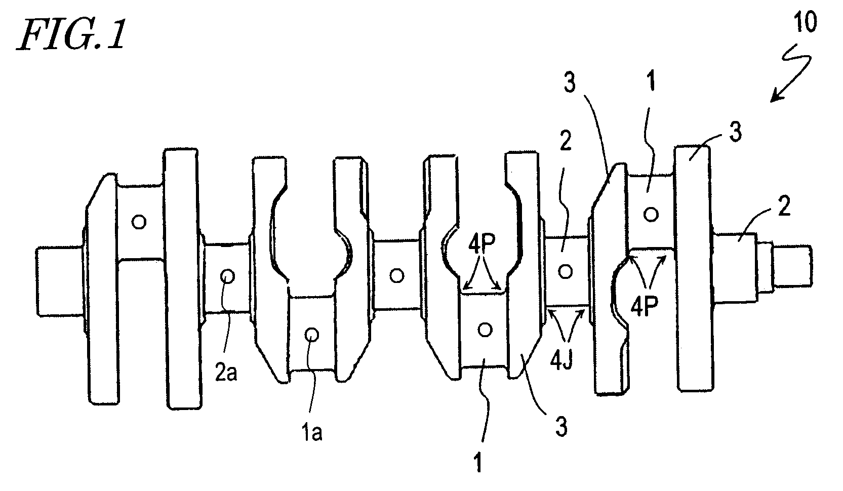
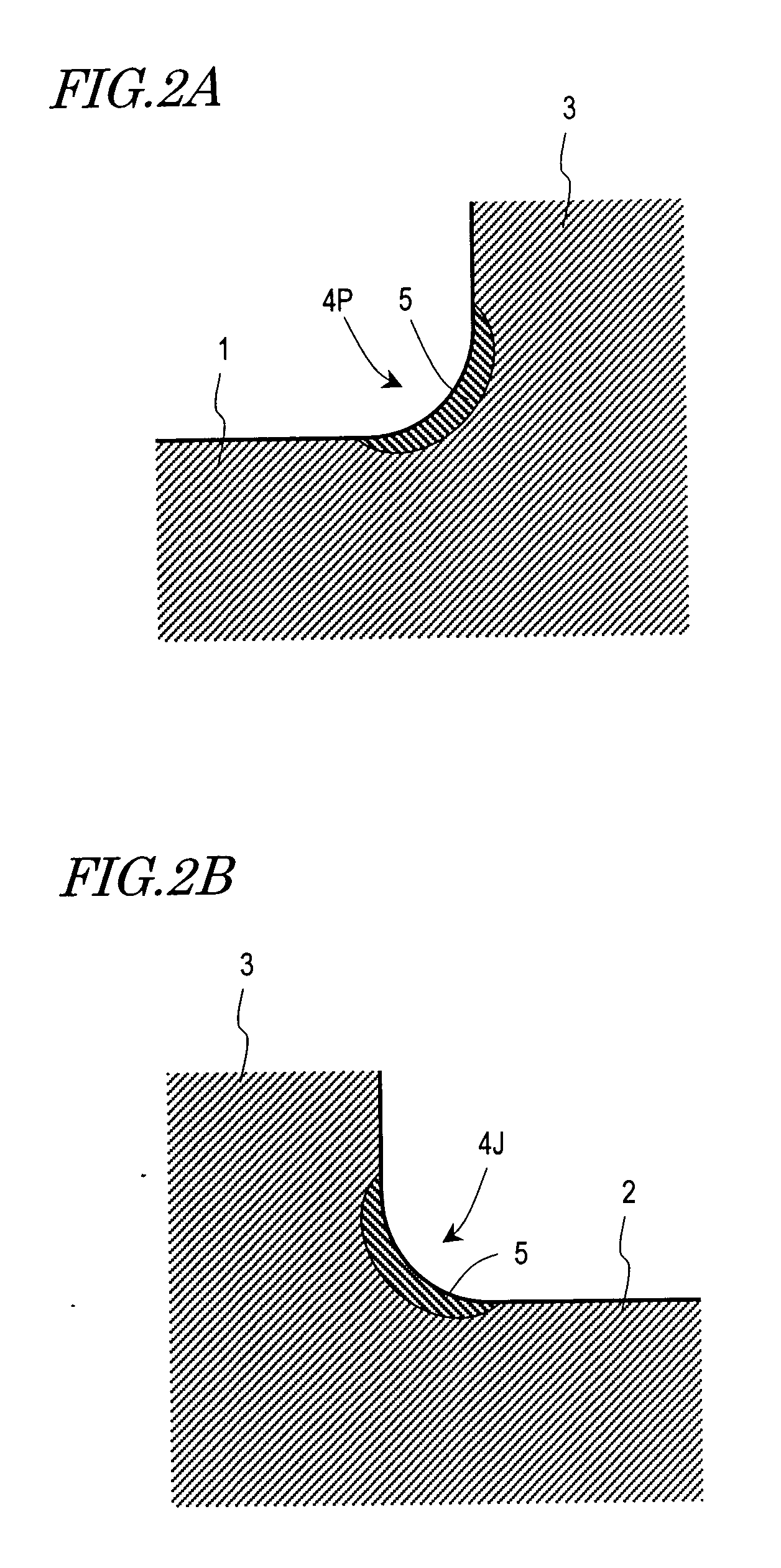
[0052]First, with reference to FIG. 1 and FIGS. 2A and 2B, the structure of the crankshaft 10 according to a preferred embodiment of the present embodiment will be described. FIG. 1 is a diagram showing the entire crankshaft 10. FIGS. 2A and 2B are enlarged cross-sectional views each showing a portion of the crankshaft 10. The crankshaft 10 is preferably formed of an iron-based alloy such as steel. As shown in FIG. 1, the crankshaft 10 includes crankpins 1, crank journals 2, and crank arms 3. The crankshaft 10 is preferably integrally formed by hot forging.
[0053]Each crankpin (hereinafter also simply referred to as a “pin”) 1 serves as an axis onto which a large end of a connecting rod is attached. On the other hand, the crank journals (hereinafter also simply referred to...
PUM
| Property | Measurement | Unit |
|---|---|---|
| Thickness | aaaaa | aaaaa |
| Thickness | aaaaa | aaaaa |
| Diameter | aaaaa | aaaaa |
Abstract
Description
Claims
Application Information
 - R&D
- Intellectual Property
- Life Sciences
- Materials
- Tech Scout
- Unparalleled Data Quality
- Higher Quality Content
- 60% Fewer Hallucinations
Browse by: Latest US Patents, China's latest patents, Technical Efficacy Thesaurus, Application Domain, Technology Topic, Popular Technical Reports.
© 2025 PatSnap. All rights reserved.Legal|Privacy policy|Modern Slavery Act Transparency Statement|Sitemap|About US| Contact US: help@patsnap.com


