Continuous liquid fuel vaporizer

a technology of liquid hydrocarbon fuel and continuous vaporization, which is applied in the direction of combustion air/fuel air treatment, machines/engines, electrochemical generators, etc., can solve the problem of hot interior walls, and achieve the effect of reducing the rate of accumulation and easy removal

Inactive Publication Date: 2008-09-25
DELPHI TECH INC
View PDF9 Cites 57 Cited by
  • Summary
  • Abstract
  • Description
  • Claims
  • Application Information

AI Technical Summary

Benefits of technology

[0009]Briefly described, a tubular vaporizer is heated from the outside, resulting in hot interior walls. Liquid fuel is passed into the tubular vaporizer and is vaporized by heat transferred through contact of the fuel with the hot interior walls. Vaporized fuel exits the tubular vaporizer. A stream of hot air is passed through the vaporizer as a carrier gas along with the vaporized fuel. The carrier air stream greatly reduces the rate of buildup of deposits on the vaporizer walls, compared to operation of the vaporizer without a carrier air stream; however, fueling of the vaporizer eventually must be shut down to remove deposits. The deposits are easily removed, and the vaporizer tube completely regenerated, by passing hot air alone through the tube for a period of time. In a preferred embodiment, two parallel-path vaporization tubes and switching means therebetween are provided for alternate use and regeneration cycles, affording a continuous flow of vaporized fuel from the apparatus.

Problems solved by technology

Briefly described, a tubular vaporizer is heated from the outside, resulting in hot interior walls.

Method used


Image

  • Continuous liquid fuel vaporizer
  • Continuous liquid fuel vaporizer
  • Continuous liquid fuel vaporizer

Examples


Embodiment Construction

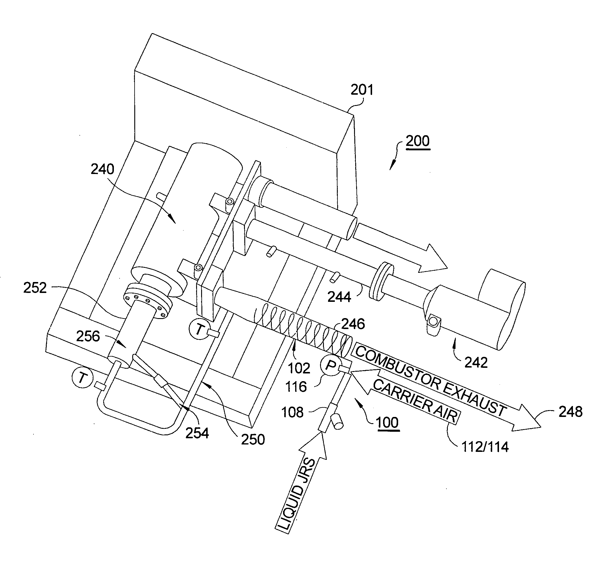
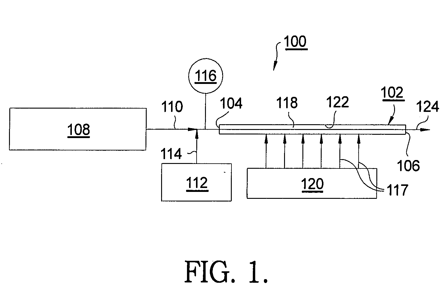
[0017]Referring to FIG. 1, a first embodiment 100 of a contact vaporizer assembly in accordance with the invention comprises a vaporizer tube 102 having an inlet 104 and an outlet 106, liquid injection means 108 for injecting a stream of a volatile liquid 110 into tube 102, air supply means 112 for injecting a carrier flow 114 of air into tube 102 either with or independently of liquid stream 110, and preferably a pressure sensing means 116 for determining back pressure at the tube inlet 104. Vaporizing of liquid 110 may be accelerated by application of heat 117 to an exterior surface 118 of tube 102 from a heat source 120, and by heating carrier air flow 114 by means (not shown) either ahead of or after air supply means 112.

[0018]Vaporizer tube 102 may be either linear or non-linear; in a presently preferred embodiment, tube 102 is helically coiled to provide greatest surface area in the shortest length of heat source 120. Tube 102 may be formed from any appropriate metal such as s...


PUM


Abstract

A tubular vaporizer for vaporizing volatile liquids, and especially hydrocarbon fuels. Liquid fuel is passed into the vaporizer tube, is vaporized by heat transferred through fuel contact with the hot walls, and vaporized fuel exits the vaporizer tube. A hot carrier air stream is passed through the vaporizer with the vaporized fuel, greatly reducing the rate of buildup of deposits on the vaporizer walls; however, fueling of the vaporizer eventually must be shut down to remove the deposits. The deposits are easily removed, and the vaporizer tube completely regenerated, by passing hot air alone through the tube for a period of time. In a preferred embodiment, two parallel-path vaporization tubes and switching means therebetween are provided for alternate use and regeneration cycles, affording a continuous flow of vaporized fuel from the apparatus. The vaporizer is especially useful in providing gaseous fuel for a catalytic hydrocarbon reformer.

Description

RELATIONSHIP TO GOVERNMENT CONTRACTS[0001]The present invention was supported in part by a U.S. Government Contract, No. DE-FC26-02NT41246. The United States Government may have rights in the present invention.TECHNICAL FIELD[0002]The present invention relates to apparatus and methods for vaporizing volatile liquid fuels; more particularly, to apparatus and methods for continuously vaporizing liquid hydrocarbon fuels; and most particularly, to a contact fuel vaporizer employing carrier air flow through, preferably, dual parallel vaporization tubes to permit periodic alternating cleaning of each tube during continuous operation of the vaporizer apparatus.BACKGROUND OF THE INVENTION[0003]Hydrocarbon reformers for catalytically converting a gaseous hydrocarbon feed source into molecular hydrogen and carbon monoxide (resulting in a gas mixture known in the art as “reformate”) are well known. One important known use for such a reformer is in providing a continuous reformate supply to a f...

Claims


Application Information

Patent Timeline
Patent Type & Authority Applications(United States)
IPC IPC(8): F02M31/02
CPCF23K5/12H01M8/0618Y02E60/525H01M2008/1293Y02E60/50H01M8/0631
Inventor WEISS, AMANDA M.SALEMI, MICHAEL R.ZITZKA, RYAN J.
Owner DELPHI TECH INC
Why Eureka
Try Eureka