Power efficient multistage amplifier and design method

a multi-stage amplifier, power efficiency technology, applied in the direction of amplifier combinations, high-frequency amplifiers, automatic tone/bandwidth control, etc., can solve the problems of large amplifiers and other conventional power efficient amplifiers, poor large output power relative to input power, so as to achieve power efficiency and desirable power transfer characteristics, good am-am and am-pm transfer characteristics, the effect of good power efficiency

Active Publication Date: 2008-09-25
VIASAT INC
View PDF4 Cites 8 Cited by
  • Summary
  • Abstract
  • Description
  • Claims
  • Application Information

AI Technical Summary

Benefits of technology

[0006]A power efficient multistage power amplifier is realized through a plurality of stages, each stage having an amplifier and a drive circuit that biases the amplifier to operate at or near the amplifier's power added efficiency (PAE) peak. The PAE peak of many amplifiers is at or near the amplifier's linear-compression transition region. In this region, the amplifiers have good AM-AM and AM-PM transfer characteristics. Use of these amplifiers in each stage of the multistage amplifier provides power efficiency and a desirable power transfer characteristic.

Problems solved by technology

A common characteristic of these conduction angle bias amplifiers is significant distortion of the output power relative to the input power.
Conventional power amplifiers such as Doherty amplifiers, Chireix out-phasing amplifiers and Envelope Elimination and Restoration (EER) amplifiers also suffer from poor AM-AM and AM-PM transfer characteristics.
Moreover, these amplifiers and other conventional power efficient amplifiers are large, complex, or expensive and have limited input ranges and bandwidths.

Method used


Image

  • Power efficient multistage amplifier and design method
  • Power efficient multistage amplifier and design method
  • Power efficient multistage amplifier and design method

Examples


Embodiment Construction

[0014]While exemplary embodiments are described herein in sufficient detail to enable those skilled in the art to practice the invention, it should be understood that other embodiments may be realized and that logical electrical and mechanical changes may be made without departing from the spirit and scope of the invention. Thus, the following detailed description is presented for purposes of illustration only.

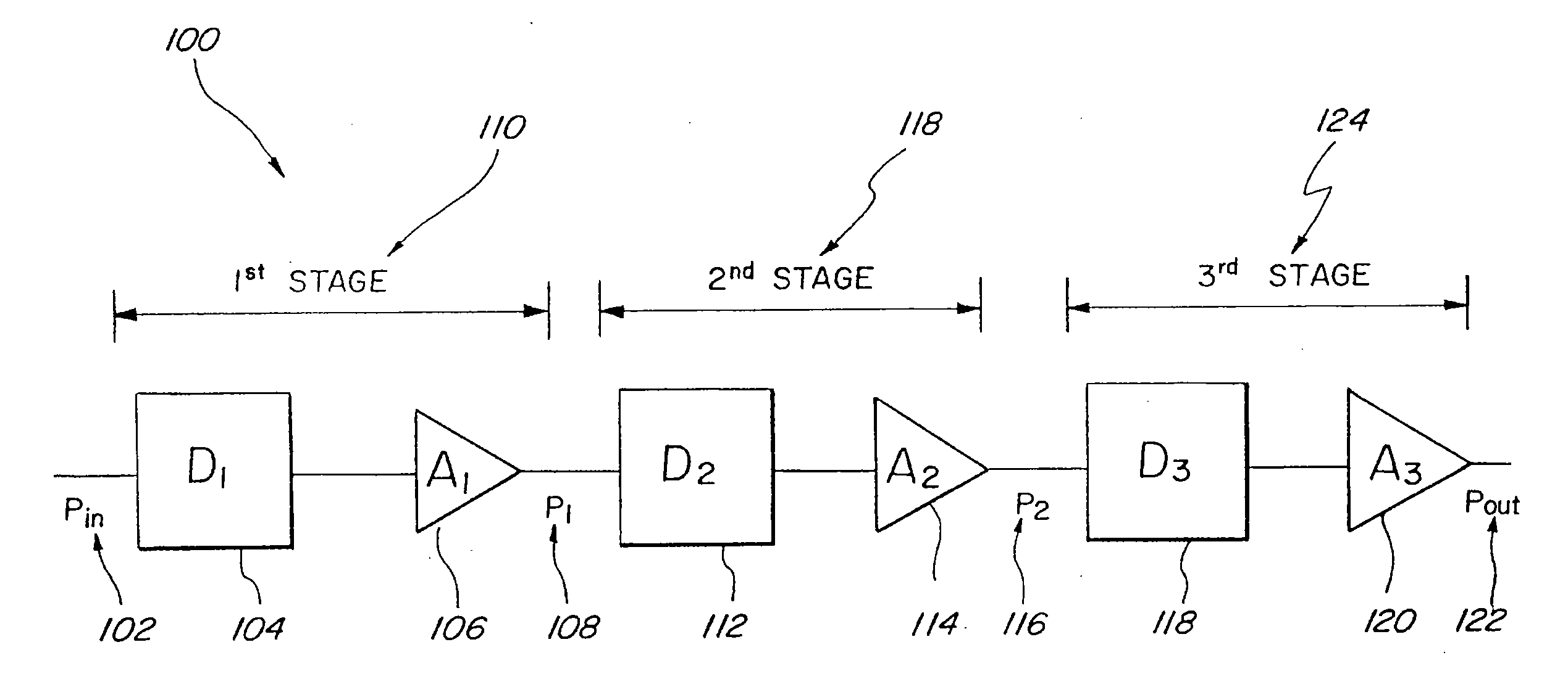
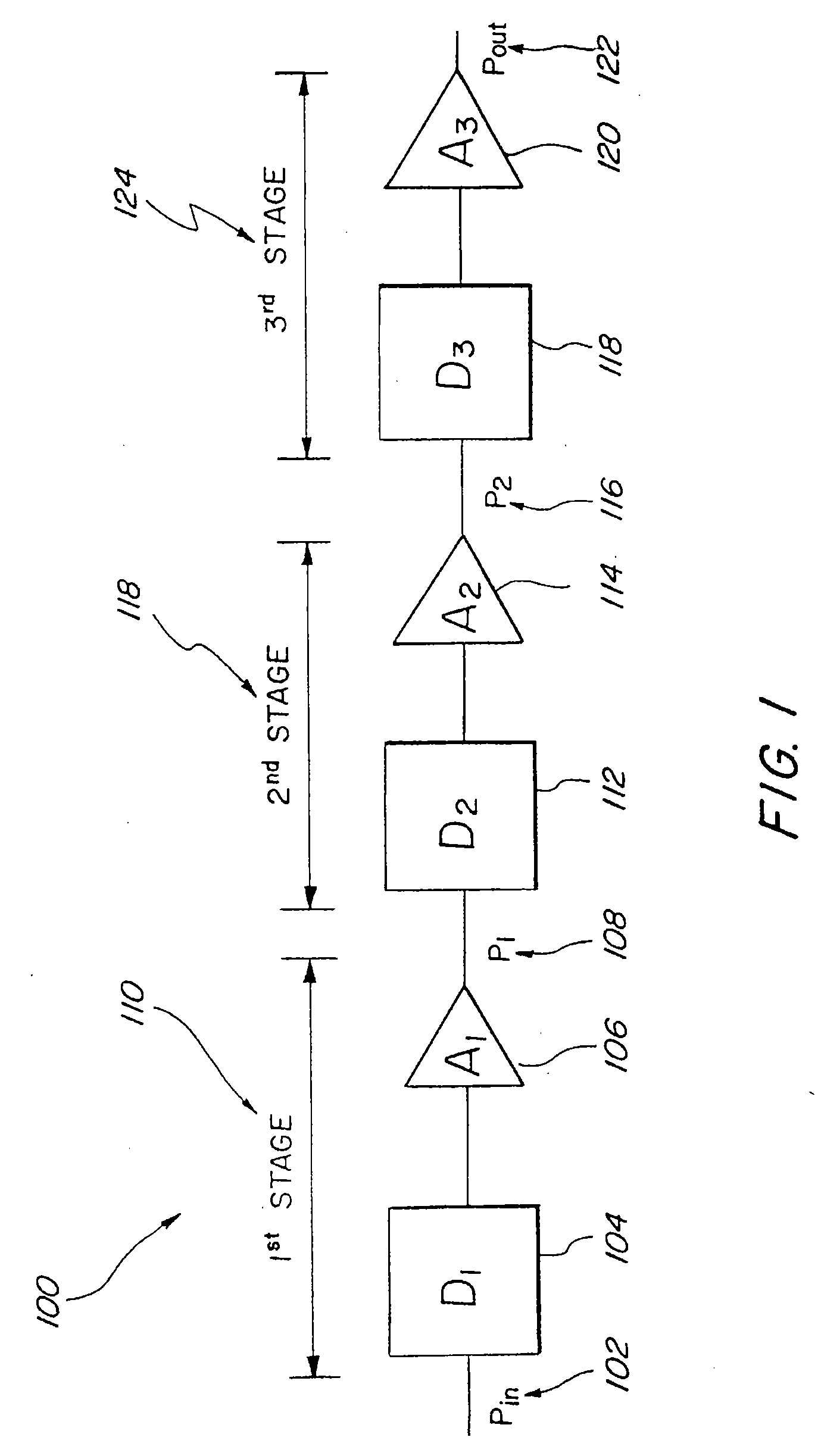
[0015]FIG. 1 shows a multistage amplifier 100 according to an exemplary embodiment of the present invention. Multistage amplifier 100 may comprise an input 102 and an output 122. In one exemplary embodiment, multistage amplifier 100 further comprises a first stage 110, a second stage 118, and a third stage 124. In this embodiment, each of the first, second, and third stages comprises an input and an output. The output 108 of first stage 110 is connected to the input of second stage 118, and the output of second stage 118 is connected to the input of third stage 124. Thus, in t...


PUM


Abstract

A multistage amplifier and design method are disclosed. The multistage amplifier has a plurality of amplifier stages, each stage having an amplifier designed and biased to operate at or near the amplifier's power added efficiency (PAE) peak. The PAE peak of each of the amplifier is at or near the amplifiers linear-compression transition region, providing a multistage power amplifier that is power efficient and has desirable amplitude to amplitude and amplitude to phase power transfer characteristics. The amplifier is designed by matching the output impedance of a final stage with a load. Amplifier stages are iteratively designed from the last stage to the first. At each stage, an amplifier and drive circuit are designed. The drive circuit and amplifier are designed to provide each stage with output impedance matched to the input impedance of the following stage and to operate at or near the PAE peak of the amplifier.

Description

FIELD OF INVENTION [0001]The present invention is related to multistage amplifiers. More particularly the invention relates to multistage amplifiers that are power efficient.BACKGROUND OF THE INVENTION [0002]Multistage amplifiers are used in many applications where power is limited. For example, most space vehicles have only solar panels and batteries for gathering and storing power for all systems on the space vehicle. Space vehicles frequently have a communication system for communicating with earth or other space vehicles. The communication system has one or more power amplifiers for amplifying signals to be transmitted. The power amplifiers are ideally very small and very power efficient to conserve space and power on the space vehicle. The power amplifiers must also be able to amplify high frequency signals, often in the microwave and millimeter wave frequency bands. Monolithic microwave integrated circuit (MMIC) technology is often used to fabricate these power amplifiers in a...

Claims


Application Information

Patent Timeline
Patent Type & Authority Applications(United States)
IPC IPC(8): H03F3/68
CPCH03F1/02H03F3/189
Inventor BUER, KENNETH V.LYONS, MICHAELDAOUD, SCARLET
Owner VIASAT INC
Why Eureka
Try Eureka