
Efficient uplink feedback in a wireless communication system

a wireless communication system and wireless communication technology, applied in multi-frequency code systems, duplex signal operations, multi-frequency communication, etc., can solve the problems of inefficient consumption of system resources, time-varying fading, frequency-selective fading,

Active Publication Date: 2008-09-25
SAMSUNG ELECTRONICS CO LTD A CHARTERED IN & EXISTING UNDER THE LAWS OF THE REPUBLIS OF KOREA
View PDF11 Cites 183 Cited by
  • Summary
  • Abstract
  • Description
  • Claims
  • Application Information

AI Technical Summary

Benefits of technology

"The present invention provides an improved method and apparatus for transmitting control channel information. The method involves jointly encoding control channel elements based on a reference signal and multiple input and multiple output rank and selected layers, and transmitting the encoded control channel elements to a receiver. The receiver then jointly decodes the control channel elements and utilizes the information for efficient transmission of control channel information. The method may include presetting indicators for multiple input and multiple output rank and selected layers, and using specific codes and modulation schemes for efficient transmission. The use of multiple modulated sequences and resource elements in time and frequency domain may further improve the efficiency of the transmission."

Problems solved by technology

In a communication system, a multi-path communication channel results in a frequency-selective fading.
Moreover, in a mobile wireless environment, the channel also results in a time-varying fading.
A significant problem with this approach is that the control information inefficiently consumes a significant amount of system resources and degrades the overall system throughput and capacity.
This results in inefficient transmission because efficient coding across multiple control types cannot be employed.
Moreover, if some type of CRC is used for error detection purposes, separate CRCs are required for each of the control information types resulting in excessive overhead.

Method used


Image

  • Efficient uplink feedback in a wireless communication system
  • Efficient uplink feedback in a wireless communication system
  • Efficient uplink feedback in a wireless communication system

Examples


first embodiment

[0096]According to the principles of the present invention, Table 1 lists eleven possible physical uplink control channel (PUCCH) formats. The PUCCH may contain seven fields: “Format”, “Subbands CQI”, “MIMO rank and selected layers”, “MIMO preceding”, “ACK / NACK”, “Reserved” and “CRC”. The PUCCH may have a total of five possible payload sizes, namely 60, 43, 36, 27 and 16 bits. We assume that the UE provides feedback when one (1), five (5) or ten (10) subbands over the total bandwidth are defined. The first possible control channel, i.e., control channel 1 carries subband CQI and subband based MIMO preceding information for the case of 10 subbands. The total payload size for control channel 1 is 60 bits. Control channel 2 carries subband CQI but no MIMO information for the case of 10 subbands. If we assume that MIMO rank information is common across the subbands, it is not necessary for the PUCCH to carry the information about the MIMO rank and the selected layers. Therefore, the num...

second embodiment

[0101]In a second embodiment according to the principles of the present invention, as shown in FIG. 16, the PUCCH is first transferred into tail bit insertion unit 210. Tails bits are a fixed sequence of bits added to the end of a block of data to reset convolutional encoder 212 to a predefined state. Then, the PUCCH is coded with a convolutional code by convolutional encoder 212. The coded information is punctured as necessary by Puncturing / Repetition unit 214. After S / P conversion by S / P conversion unit 216, the information is modulated by modulator 218 using Quadrature Phase-Shift Keying (QPSK) modulation. A Constant Amplitude Zero Autocorrelation (CAZAC) sequence modulator 220 further modulates the complex modulated symbols using a CAZAC sequence. CAZAC sequence is used as an example and modulation with other sequences is also possible. An FFT operation is performed by FFT transformer 222 on the modulated CAZAC sequence and the resulting samples are mapped by mapping unit 224 to...

fourth embodiment

[0104]In a fourth embodiment according to the principles of the present invention shown in FIG. 20, the PUCCH is mapped to four subframes with one RB used in each subframe. Each CAZAC sequence is of a length of 12 and is mapped to 12 subcarriers. There are 12 SC-FDMA blocks within a subframe. Therefore, 12 CAZAC sequences are carried within a subframe. Each subframe carries twelve modulated CAZAC sequences with four subframes carrying forty-eight modulated CAZAC sequences. This allows for exploiting some time-diversity in the transmission of PUCCH. Also, for smaller bandwidths the total number of RBs is small and therefore spreading the PUCCH in time allows using smaller number of RBs per subframe.


PUM


Abstract

A method for transmitting control information by transmitting a reference signal from a first transceiver to a second transceiver, in response to the reception of the reference signal, determining at the second transceiver a plurality of control channel elements based upon the received reference signal, jointly encoding the plurality of control channel elements at the second transceiver to generate a control signal, and transmitting the control signal from the second transceiver to the first transceiver.

Description

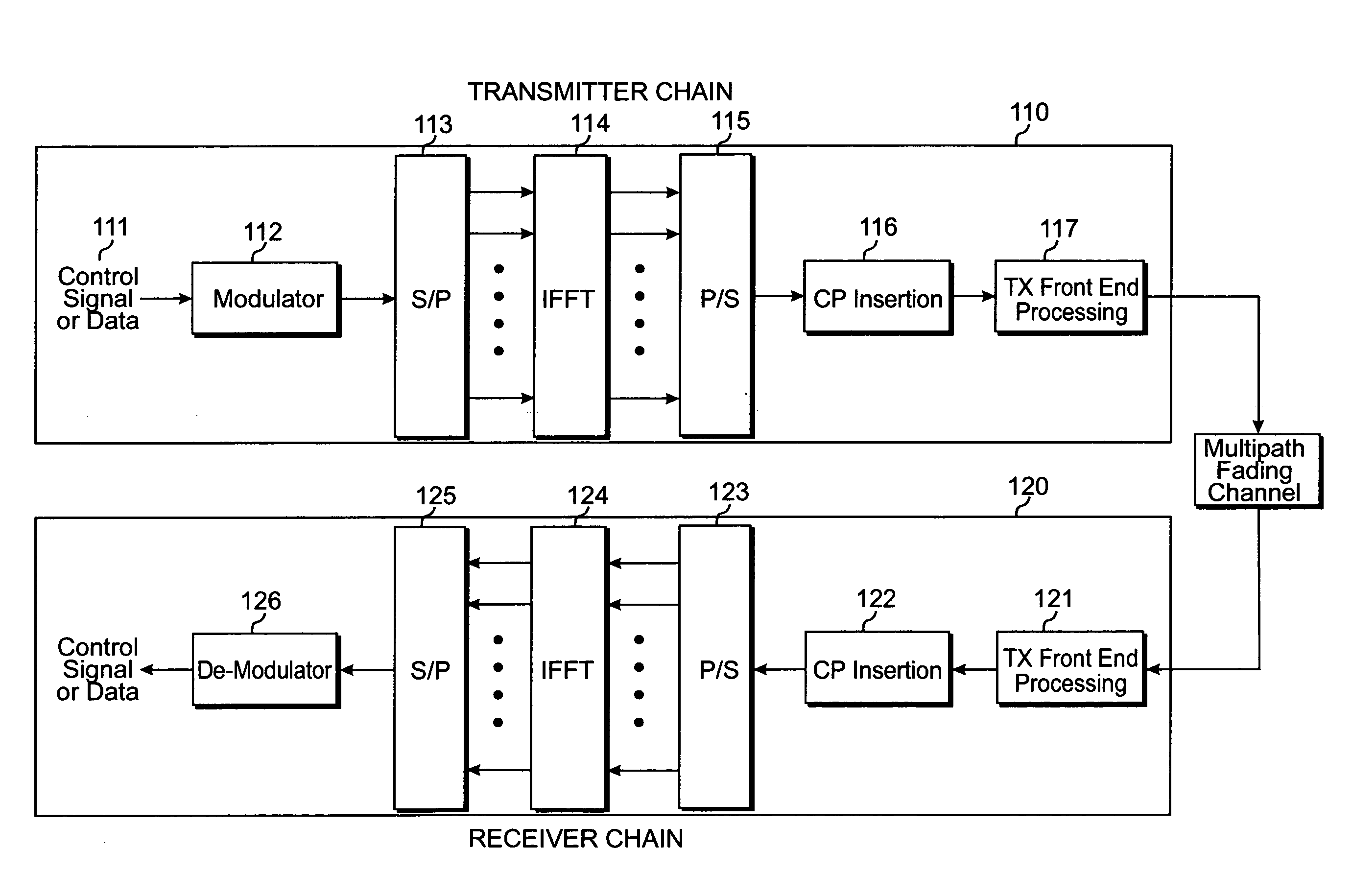
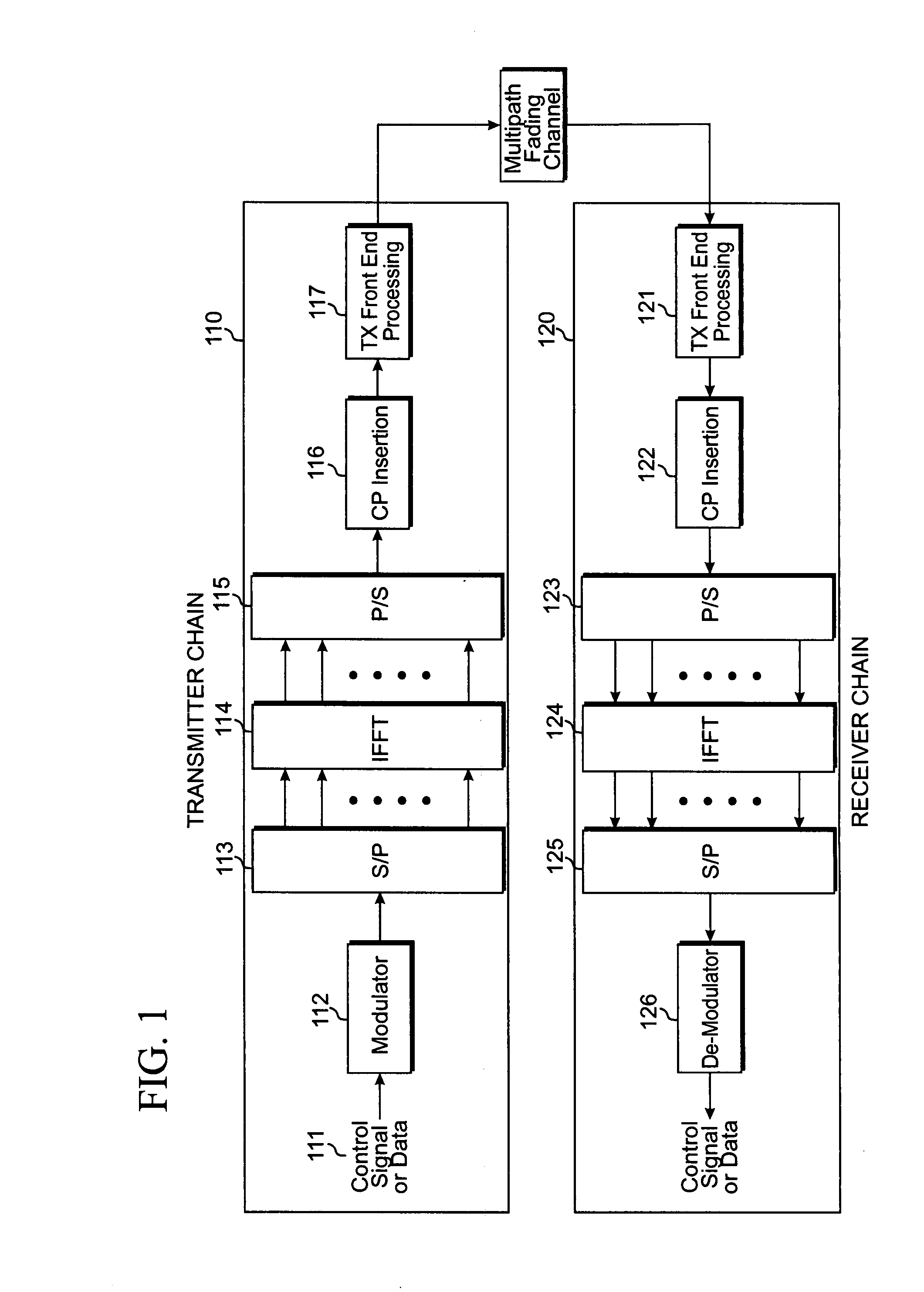
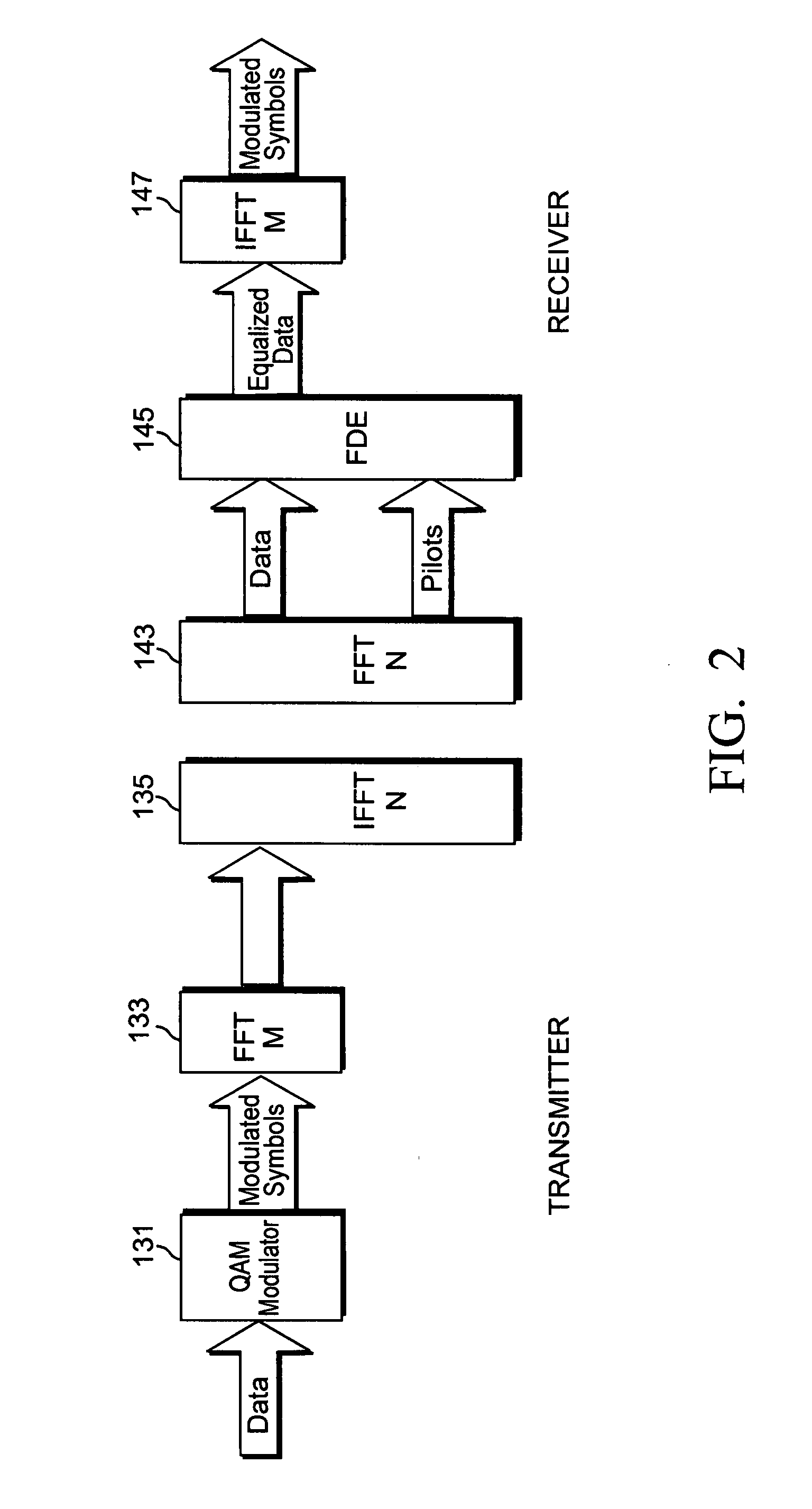
CLAIM OF PRIORITY[0001]This application makes reference to, incorporates the same herein, and claims all benefits accruing under 35 U.S.C. § 119 from a provisional application earlier filed in the U.S. Patent & Trademark Office on 21 Mar. 2007 and there duly assigned Ser. No. 60 / 919,311.BACKGROUND OF THE INVENTION[0002]1. Field of the Invention[0003]The present invention relates to a method for control channel transmission in a wireless communication system, and more specifically, a method for coding and mapping control channel information in a wireless communication system.[0004]2. Description of the Related Art[0005]Orthogonal Frequency Division Multiplexing (OFDM) is a popular wireless communication technology to multiplex data in frequency domain.[0006]In a communication system, a multi-path communication channel results in a frequency-selective fading. Moreover, in a mobile wireless environment, the channel also results in a time-varying fading. Therefore, in a wireless mobile ...

Claims


Application Information

Patent Timeline
Patent Type & Authority Applications(United States)
IPC IPC(8): H04B1/38
CPCH04L25/03343H04L2025/03802H04L2025/03426H04L2025/03414
Inventor KHAN, FAROOQPI, ZHOUYUE
Owner SAMSUNG ELECTRONICS CO LTD A CHARTERED IN & EXISTING UNDER THE LAWS OF THE REPUBLIS OF KOREA
Learn More