Polarization-multiplexing optical transmitter polarization-multiplexing optical receiver, polarization-multiplexing optical transceiving system, and controlling method thereof

Inactive Publication Date: 2008-09-25
FUJITSU LTD
View PDF18 Cites 117 Cited by
  • Summary
  • Abstract
  • Description
  • Claims
  • Application Information

AI Technical Summary

Benefits of technology

[0009]According to still another aspect of the present invention, a polarization-multiplexing optical receiver includes a polarization controller that controls polarization states of externally received polarization-multiplexing signals; a polarization splitter that splits, upon respectively extracting, from the polarization-multiplexing signals of which the polarization states are controlled by the polarization controller, a first polarization component and a second polarization component orthogonal to each other; a first optical receiving unit that receives the first polarization component split by the polarization splitter, and externally transmits a first input signal detected from the first polarization components; a second optical receiving unit

Problems solved by technology

However, on the receiving side, adding a function that performs a complex signaling process is required.
Due to this, a structure of a transmitter becomes complicated.
Furthermore, by adding the control bit-string, because a mark ratio of each polarization channel vari

Method used


Image

  • Polarization-multiplexing optical transmitter polarization-multiplexing optical receiver, polarization-multiplexing optical transceiving system, and controlling method thereof
  • Polarization-multiplexing optical transmitter polarization-multiplexing optical receiver, polarization-multiplexing optical transceiving system, and controlling method thereof
  • Polarization-multiplexing optical transmitter polarization-multiplexing optical receiver, polarization-multiplexing optical transceiving system, and controlling method thereof

Examples


first embodiment

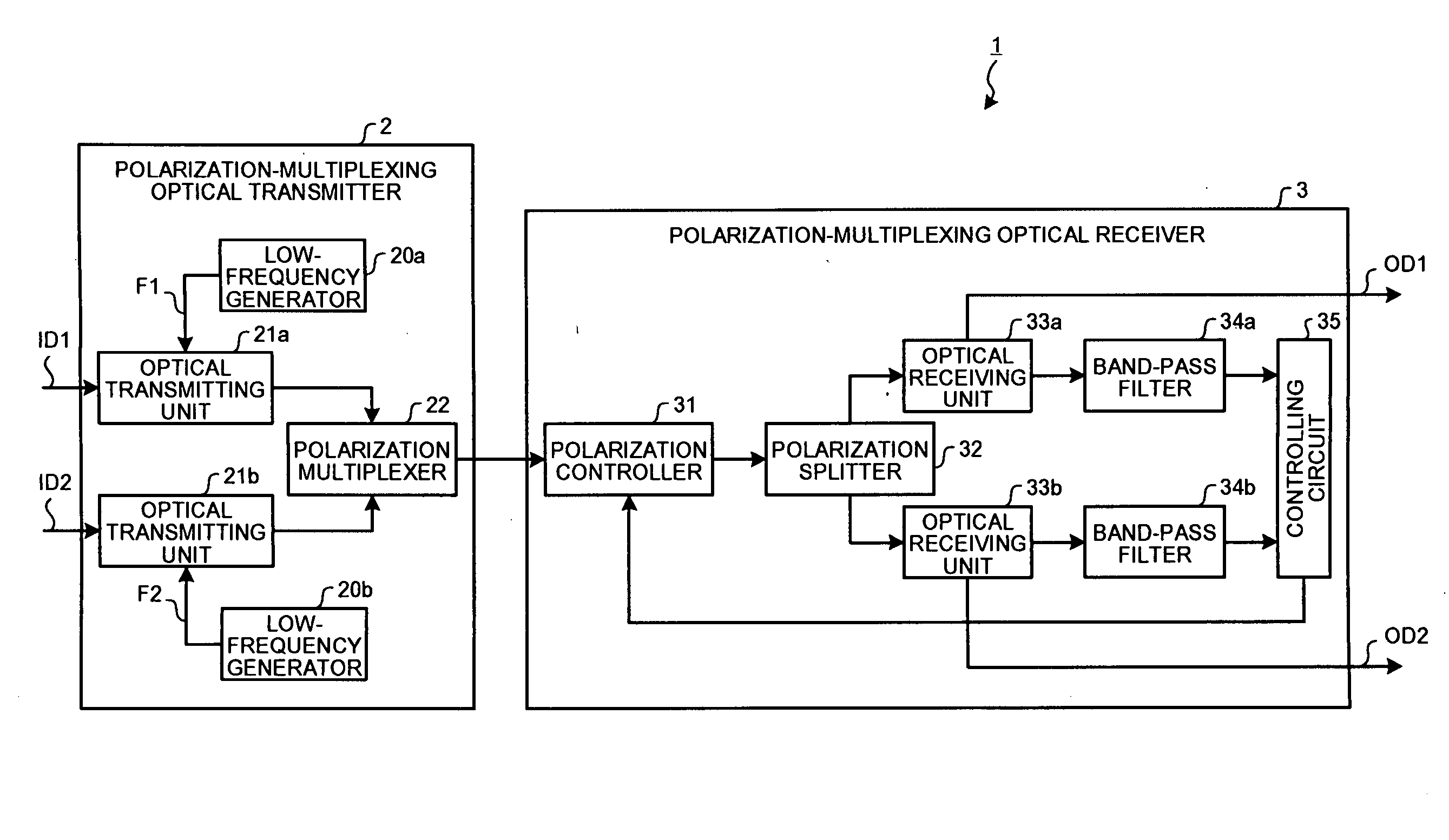
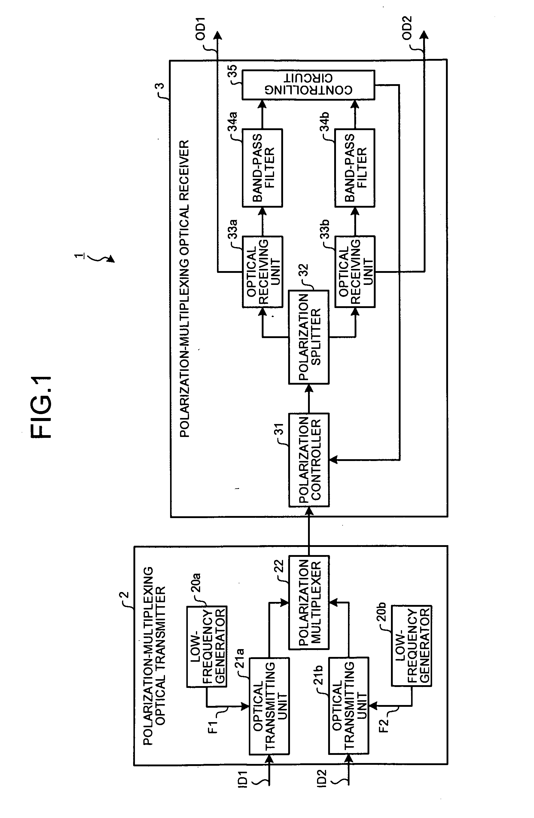
[0026]A structure of a polarization-multiplexing optical transceiving system according to a present embodiment is explained first. FIG. 1 is a block diagram of a polarization-multiplexing optical transceiving system according to a As shown in FIG. 1, a polarization-multiplexing optical transceiving system 1 includes a polarization-multiplexing optical transmitter 2 and a polarization-multiplexing optical receiver 3. The polarization-multiplexing optical transmitter 2 and the polarization-multiplexing optical receiver 3 are connected by an optical transmission line of a wavelength division multiplexing system (WDM).

[0027]The polarization-multiplexing optical transmitter 2 includes low-frequency generators 20a and 20b, optical transmitting units 21a and 21b, and a polarization multiplexer (polarization beam combiner (PBC)) 22. The optical transmitting units 21a and 21b and the polarization multiplexer 22 are respectively connected by a polarization maintaining fiber (PMF).

[0028]The l...

second embodiment

[0064]In the second embodiment, the correlation is determined by using the components of the fixed waveform signals F3 included in the two signals. In other words, a value of the signals output from the multipliers 36a and 36b increases when more and more components of the fixed waveform signals F3 are included in the signals output from the optical receiving units 33a and 33b and the correlation is determined as high. However, the value of the signals output from the multipliers 36a and 36b becomes small when the components of the fixed waveform signals F3 are not included in the signals output from the optical receiving units 33a and 33b and the correlation is determined as low.

[0065]In the optical receiving unit 33a according to the second embodiment, it is desirable to input all the signals transmitted from the optical transmitting unit 21a in which the fixed waveform signals F3 are input. Thus, it is desirable to control the signals such that the value of the signals output fro...

third embodiment

[0072]It is desirable that the signals output from the optical receiving unit 33ta correspond to the signals transmitted from the optical transmitting unit 21a and the signals output from the optical receiving unit 33tb correspond to the signals transmitted from the optical transmitting unit 21b. Furthermore, the signals transmitted from the optical transmitting unit 21a and the signals transmitted from the optical transmitting unit 21b include separate data. Thus, a minimum correlation value is desirable upon multiplying and averaging the signals output from the optical receiving unit 33ta and the signals output from the optical receiving unit 33tb. In the third embodiment, more and more common components are included in the two signals when an anticipated value of the correlation increases. Thus, the polarization-multiplexing signals cannot be stably split.

[0073]A controlling circuit 35t according to the third embodiment generates the feedback control signals for minimizing the va...


PUM


Abstract

By using low-frequency signals, an optical transmitting unit modulates one of a wavelength, a transmission timing, and an intensity of light as a carrier wave. A polarization multiplexer synthesizes the output light signals, modulated by the optical transmitting unit, in polarization states orthogonal to each other and generates polarization-multiplexing signals. A polarization splitter splits by extracting two orthogonal polarization components from the polarization-multiplexing signals. The polarization states of the polarization-multiplexing signals are controlled by a polarization controller in an optical receiving unit. A band-pass filter extracts components transmitting through passbands from output signals of the optical receiving unit and outputs an intensity of the components. Based on the intensity output from the filter, a controlling circuit generates feedback control signals for maximizing a ratio of the components of the low-frequency signals and by using the feedback control signals, the polarization controller controls the polarization states of the optical multiplexing signals.

Description

BACKGROUND OF THE INVENTION[0001]1. Field of the Invention[0002]The present invention relates to a polarization-multiplexing optical transmitter, a polarization-multiplexing optical receiver, a polarization-multiplexing optical transceiving system, and a controlling method thereof useful for transmission using polarization multiplexing, and, more particularly to a polarization-multiplexing optical transmitter, a polarization-multiplexing optical receiver, a polarization-multiplexing optical transceiving system, and a controlling method thereof that can stably split polarization components.[0003]2. Description of the Related Art[0004]For implementing an ultra-high speed optical transmission system of more than or equal to 40 gigabits per second (Gbit / s), a polarization multiplexing technology has attracted considerable interest. In the polarization multiplexing technology, two polarization states that are orthogonal to each other are available in a same wavelength signal and by using...

Claims


Application Information

Patent Timeline
IPC IPC(8): H04B10/00H04B10/04H04B10/06H04B10/532H04B10/54H04J14/00H04J14/04H04J14/06
CPCH04J14/06H04B10/532
Inventor HOSHIDA, TAKESHIRASMUSSEN, JENS
Owner FUJITSU LTD
Why Eureka
Try Eureka