Abrasive articles, rotationally reciprocating tools, and methods

a technology of rotating reciprocating tools and abrasives, which is applied in the field of abrasive articles, rotationally reciprocating tools, and methods, can solve the problems of affecting the appearance affecting the quality of the orange-peel finish, and flat spots in the characteristic orange-peel appearance, so as to reduce the disturbance of the orange-peel texture around the defect, and the effect of repairing surface defects

Inactive Publication Date: 2008-09-25
3M INNOVATIVE PROPERTIES CO
View PDF92 Cites 36 Cited by
  • Summary
  • Abstract
  • Description
  • Claims
  • Application Information

AI Technical Summary

Benefits of technology

[0011]In contrast, the abrasive articles and rotationally reciprocating tools of the present invention may provide a user with the ability to repair surface defects in a fraction of the time required in the conventional 5-step process. Using the present invention, defects may be repaired (with limited impact on the orange-peel texture) by sanding (by rotationally reciprocating the abrasive articles and tools described herein) followed by one or more polishing operations. It may be preferred that the sanding be followed by an initial polishing step, followed by at least one subsequent polishing operation to remove s

Problems solved by technology

During application of each of these coats, or during repair thereof, dust, dirt or other particles may, however, get caught in the finish, resulting in defects such as protrusions, etc. in the finish (commonly referred to as “nibs”).
The defects typically detract from the appearance of the orange-peel finish to a degree that is not acceptable.
As a result, the repairs themselves may cause flat spots in the characteristic orange-peel appearance of areas adjacent to the removed defec

Method used


Image

  • Abrasive articles, rotationally reciprocating tools, and methods
  • Abrasive articles, rotationally reciprocating tools, and methods
  • Abrasive articles, rotationally reciprocating tools, and methods

Examples


example 1

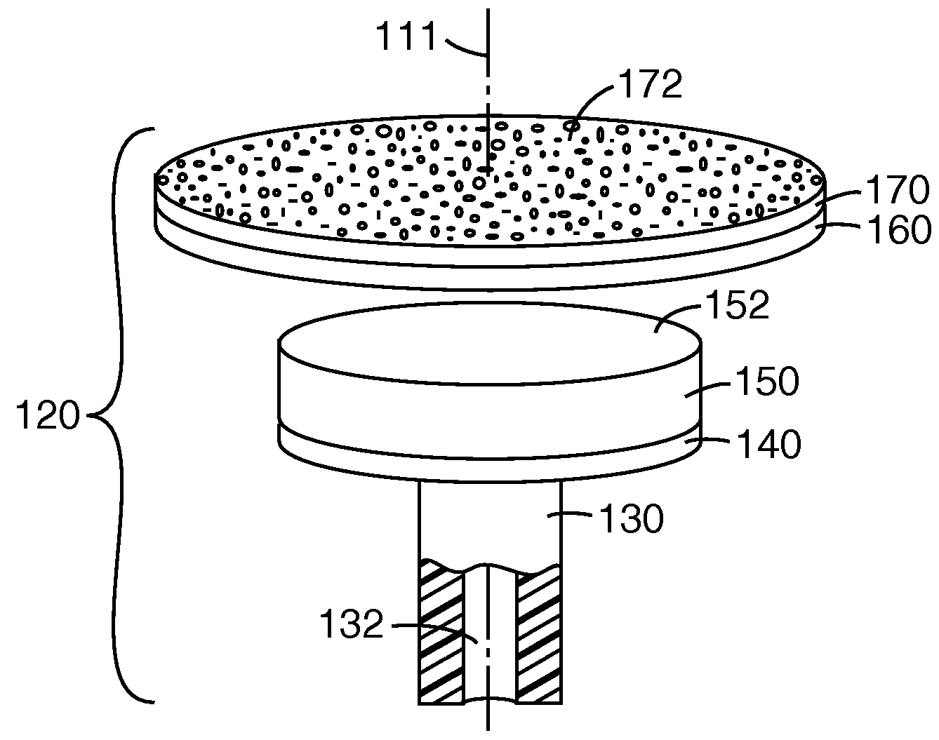
[0145]An abrasive article was manufactured using transfer adhesive (commercially available under the trade designation “9453LE” from 3M Company) that was applied to the non-abrasive face of a 0.5 inch (1.27 cm) diameter structured abrasive member (manufactured as described above). The larger 0.5 inch diameter abrasive member was centered over and attached to the smaller 0.25 inch diameter mounting surface of the base plate assembly. The abrasive article of Example 1 thus included the following components depicted in FIG. 4: the base plate 140 and abrasive member 170 attached directly to the base plate 140. The abrasive article was then used as described in Sanding Test No. 1 below.

example 2

[0146]An abrasive article was manufactured by die-cutting a 0.5 inch (1.27 cm) diameter polyvinyl foam disc, 0.027 inch (0.69 mm) thick from an adhesive bandage commercially available under the trade designation NEXCARE ADHESIVE STRIP BANDAGE from 3M Company. The adhesive liner was removed and the adhesive face of the foam disc was attached to the non-abrasive major surface of a 0.5 inch diameter structured abrasive member (manufactured as described above). The transfer adhesive of Example 1 was then applied to the non-adhesive face of the foam disc. The transfer adhesive-coated major surface of the larger 0.5 inch diameter polyvinyl foam disc (with its attached structured abrasive member) was then centered over and attached to the smaller 0.25 inch diameter mounting surface of the base plate assembly. The abrasive article of Example 2 thus included the following components depicted in FIG. 4: the base plate 140, support layer 160 (polyvinyl foam disc), and abrasive member 170. The ...

example 3

[0147]An abrasive article was made according to the method described in Example 2, except that the 0.5 inch (1.27 cm) diameter polyvinyl foam was replaced by a 5 / 16 inch (7.9 mm), 0.090 inch (2.29 mm) thick disc of polyurethane foam, commercially available under the trade designation “R600U-090” from Illbruck Company, Minneapolis, Minn. The larger 0.5 inch diameter structured abrasive member was centered over the smaller 5 / 16 inch diameter polyurethane foam disc. The 5 / 16 inch diameter polyurethane foam disc was centered on the 0.25 inch diameter mounting surface of the base plate assembly. The abrasive article of Example 3 thus included the following components depicted in FIG. 4: the base plate 140, compressible member 150 (polyurethane foam disc), and abrasive member 170. The abrasive member 170 was attached directly to the compressible member 150. The abrasive article was then used as described in Sanding Test No. 1 below.


PUM

PropertyMeasurementUnit
Angleaaaaaaaaaa
Angleaaaaaaaaaa
Areaaaaaaaaaaa

Abstract

Methods of abrading surfaces by rotationally reciprocating abrasive surfaces in contact with the surfaces, abrasive articles for use in rotationally reciprocating tools, and methods of removing defects in a surface, where the methods include sanding using a rotationally reciprocating abrasive surface followed by one or more polishing operations are disclosed.

Description

[0001]To protect and preserve the aesthetic qualities of the finish on an automobile or other vehicle, it is generally known to provide a clear (non-pigmented or slightly pigmented) topcoat over a colored (pigmented) basecoat, so that the basecoat remains unaffected even during prolonged exposure to the environment or weathering. Generally in the art, this is known as a basecoat / topcoat or basecoat / clearcoat finish. The resulting finish is not typically completely smooth (due to, e.g., the spraying conditions, the composition of the topcoat or clearcoat, drying conditions, topography of the underlying surface, etc.). Rather than being perfectly smooth, the clearcoat or topcoat finish typically exhibits a texture that is somewhat similar to the texture seen in the peel of an orange. That texture is commonly referred to as an “orange-peel” finish and is acceptable in most situations.[0002]During application of each of these coats, or during repair thereof, dust, dirt or other particle...

Claims


Application Information

Patent Timeline
IPC IPC(8): B24B1/00
CPCB24D9/08B24B23/04
Inventor ANNEN, MICHAEL JOHNFELIPE, PETER ATANACIO
Owner 3M INNOVATIVE PROPERTIES CO
Why Eureka
Try Eureka