Brake control apparatus and pump-up system

Inactive Publication Date: 2008-09-25
HITACHI LTD
View PDF12 Cites 54 Cited by
  • Summary
  • Abstract
  • Description
  • Claims
  • Application Information

AI Technical Summary

Benefits of technology

[0004]It is, therefore, in view of the previously-described disadvantages of the prior art, an object of the invention to provide a brake control apparatus ca

Problems solved by technology

However, owing to working fluid leaked out of the hydraulic brake system (e.g., the failed wheel-brake cylinder), there is a possibility that a wheel cylinder pressure in

Method used


Image

  • Brake control apparatus and pump-up system
  • Brake control apparatus and pump-up system
  • Brake control apparatus and pump-up system

Examples


first embodiment

[0031]Referring now to the drawings, particularly to FIGS. 1-8D, there is shown the brake control apparatus of the first embodiment.

[0032][Brake System Configuration]

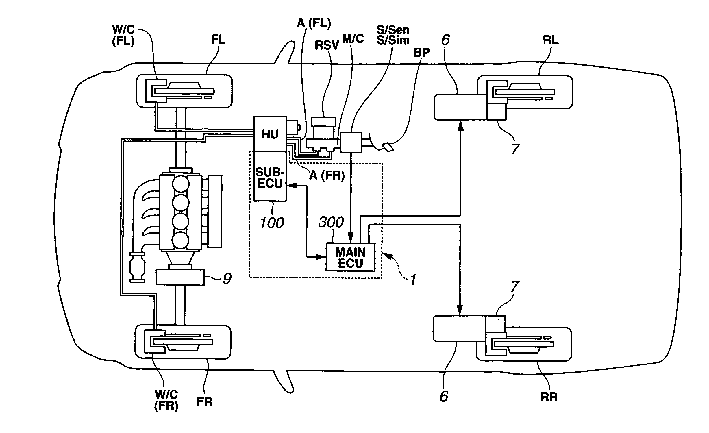
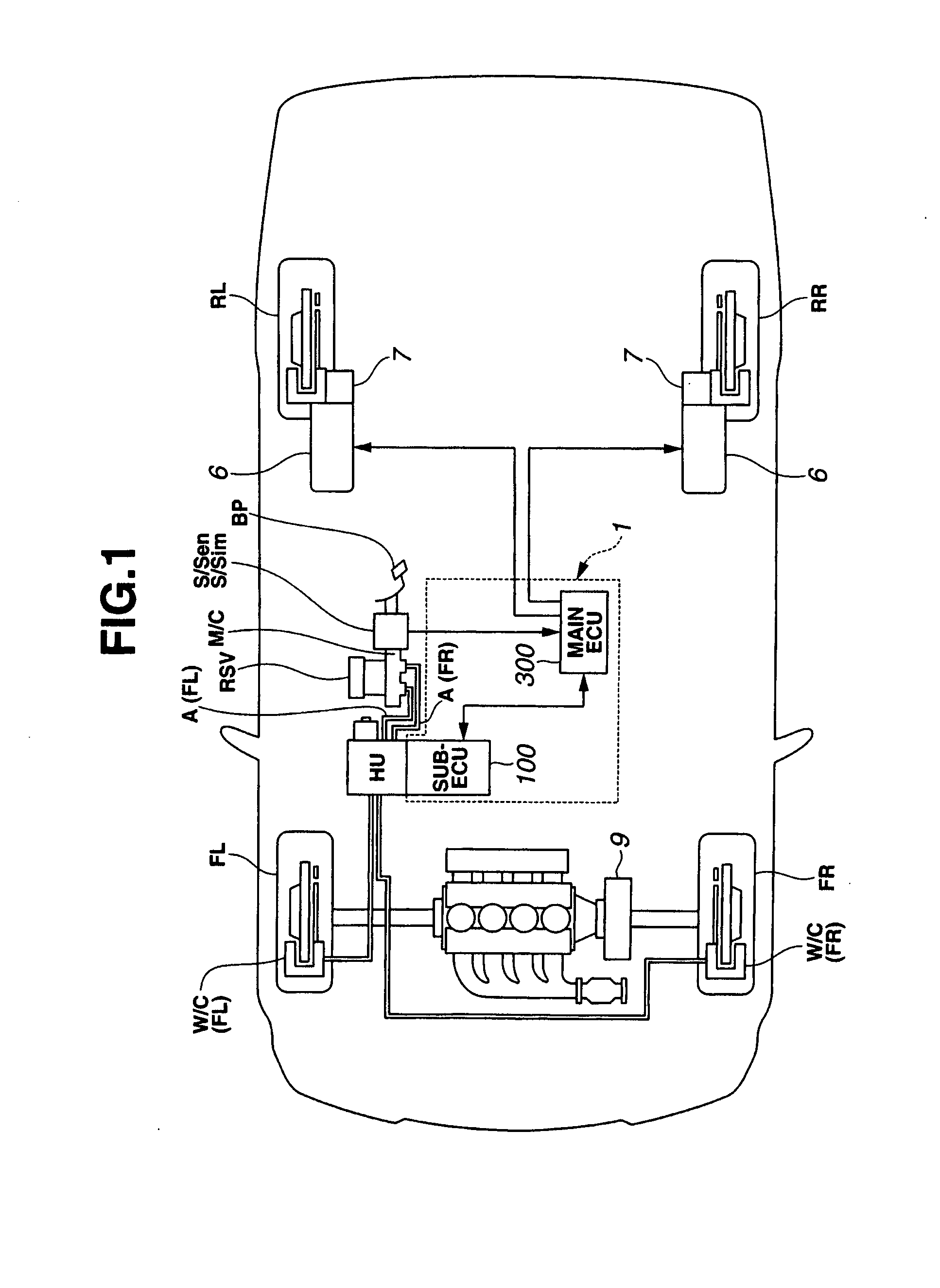
[0033]FIG. 1 shows the brake control system configuration of the brake control apparatus of the first embodiment. The brake control apparatus of FIG. 1 is exemplified in a brake-by-wire (BBW) system equipped brake device employing a common hydraulic unit (or a common hydraulic modulator) HU configured to regulate or modulate working fluid pressures Pfl and Pfr for only front-left and front-right wheel-brake cylinders W / C(FL) and W / C(FR) by a pump discharge pressure, independently of a manipulation (a depression) of a brake pedal BP by the driver.

[0034]Hydraulic unit HU common to front-left and front-right hydraulic brakes is driven by means of a sub-electronic control unit (sub-ECU) 100. On the other hand, regarding each of rear brakes for rear-left and rear-right road wheels RL-RR, a dynamo-electric brake (or an electr...

second embodiment

[0129]Referring now to FIGS. 9-14, there is shown the brake control apparatus of the second embodiment. The fundamental concept for abnormality detection (or leak detection) of the second embodiment is the same as the first embodiment. The previously-discussed first embodiment is exemplified in a two-wheel brake-by-wire system equipped brake device in a four-wheeled vehicle with two front hydraulic wheel brakes and two rear dynamo-electric brakes, for BBW control for only front road wheels FL-FR. On the other hand, the second embodiment is exemplified in a four-wheel brake-by-wire system equipped brake device in a four-wheeled vehicle with two rear hydraulic wheel brakes as well as two front hydraulic wheel brakes.

[0130][Brake System Configuration]

[0131]FIG. 9 shows the brake control system configuration of the brake control apparatus of the second embodiment. FIG. 10 shows a hydraulic circuit diagram of the common hydraulic unit HU employed in the brake control apparatus of the sec...

third embodiment

[0212]Referring now to FIGS. 15-17, there is shown the brake control apparatus of the third embodiment. The previously-described second embodiment is exemplified in a four-wheel brake-by-wire system equipped brake device in which wheel cylinder pressures of four road wheel-brake cylinders W / C(FL)-W / C(RR) are all built up by means of a single pump, that is, either main pump Main / P such as a gear pump built in hydraulic unit HU (see FIG. 10) or sub-pump Sub / P. On the other hand, the third embodiment is exemplified in a rear-wheel brake-by-wire system equipped brake device in which fluid pressure control of front wheel-brake cylinders W / C(FL)-W / C(FR) and fluid pressure control of rear wheel-brake cylinders W / C(RL)-W / C(RR) are performed independently of each other by means of respective pumps P1 and P2. In the third embodiment, the first pump P1 is driven by a first motor M1 and comprised of a tandem plunger pump installed in a first hydraulic unit HU1, whereas the second pump P2 is dri...


PUM


Abstract

A brake control apparatus of an automotive vehicle employs a pump incorporated in a hydraulic actuator, a separate pressure control valve disposed between the pump and each individual wheel-brake cylinder and having an orifice having a predetermined orifice-constriction flow passage area, and vehicle sensors including at least wheel cylinder pressure sensors. Also provided is a controller configured to be connected to the vehicle sensors and the hydraulic actuator, for calculating, based on a driver's manipulated variable, target wheel cylinder pressures, and for controlling the hydraulic actuator responsively to the target wheel cylinder pressures. The controller is further configured for calculating a fluid-pressure deviation between the target wheel cylinder pressure and the actual wheel cylinder pressure, and for stopping working-fluid supply from the pump to the abnormal wheel-brake cylinder having an abnormality in the fluid-pressure deviation exceeding a predetermined threshold value.

Description

TECHNICAL FIELD[0001]The present invention relates to a pump-up system that pressurizes working fluid by means of a pump, and specifically to a brake control apparatus capable of controlling a braking force by regulating each individual wheel-brake cylinder pressure by means of a brake-by-wire (BBW) control system.BACKGROUND ART[0002]In recent years, there have been proposed and developed various automobile brake devices capable of executing brake-by-wire (BBW) control. One such BBW system equipped brake device has been disclosed in Japanese Patent No. 3409721 (hereinafter is referred to as “JP3409721”), corresponding to U.S. Pat. No. 6,913,326. In the brake device disclosed in JP3409721, a brake pedal is shut off from each individual wheel-brake cylinder, a master-cylinder pressure sensor is provided to detect a master-cylinder pressure, a stroke simulator is disposed between the brake pedal and the master cylinder, and a stroke sensor is provided to detect a depression stroke of t...

Claims


Application Information

Patent Timeline
IPC IPC(8): G06F19/00B60T8/17B60T17/18
CPCB60T1/10B60T8/4072B60T8/4081B60T8/267B60T13/161B60T13/686B62D5/065B60T8/445
Inventor IWASAKI, KATSUYAKAJIYAMA, KEIGOOOSAWA, TOSHIYA
Owner HITACHI LTD
Why Eureka
Try Eureka