Abnormality Diagnosing Apparatus and Abnormality Diagnosing Method

a diagnostic apparatus and abnormality technology, applied in the direction of vibration measurement in solids, machine part testing, special data processing applications, etc., can solve the problem of high degree of damage of rotating parts, urgent maintenance, and inability to use rotating parts continuously, so as to prevent an erroneous diagnosis and prevent the effect of erroneous diagnosis and high reliability

Active Publication Date: 2008-09-25
NSK LTD
View PDF2 Cites 203 Cited by
  • Summary
  • Abstract
  • Description
  • Claims
  • Application Information

AI Technical Summary

Benefits of technology

[0118]According to the invention of (1), information of temperature and vibration, which is generated in accordance with a state of rotating the rotating part or a state of sliding the sliding part, are simultaneously detected; presence or absence of the abnormality and the degree of the damage are simultaneously determined based on the combination of the measured result by the vibration system sensor and the measured result by the temperature sensor. Therefore, the degree of the damage utilizing a characteristic of an abnormal mode of the rotating or sliding part with regard to the vibration and temperature, can be determined. Further, the abnormality diagnosis having high reliability can be carried out by preventing an erroneous diagnosis by an influence of abrupt disturbance noise or the like. Furthermore, since presence or absence of the abnormality and the degree of the damage can simultaneously be inspected in an actual operating state without disassembling the machine equipment comprising the rotating or sliding part, an optimum timing of interchanging the rotating part can be known, and efficient maintenance can be carried out.
[0119]According to the invention of (3), the abnormality of the part is diagnosed based on the detecting signal of vibration or temperature by the sensor when the rotating or sliding part is operated by inertia within the predetermined speed range when a power of the driving unit is turned off. Therefore, the abnormality of the part can be diagnosed in the actual operating state without disassembling the machine equipment comprising the rotating or sliding part, the signal can be detected with high sensitivity and high SN ratio (signal to noise ratio) by restraining the electric disturbance noise of the driving unit.
[0120]Further, according to the invention of (4), when the rotating part is rotated within the rotational speed zone equal to or faster than 100 min−1 and equal to or slower than 1500 min−1, the abnormality of the rotating part is diagnosed based on the detecting signal of vibration or temperature by the sensor. Therefore, since the abnormality of the rotating part can be diagnosed in the actual operating state without disassembling the machine equipment integrated with the rotating part, a vibrating force by a damage of flaking of the bearing or flat wear of a wheel or the like can be detected with high SN ratio, thus the abnormality diagnosis having high reliability can be carried out.
[0121]According to the invention of (11) and (32), a peak of the spectrum larger the reference value, which is calculated based on the spectrum provided by analyzing the frequency

Problems solved by technology

Meanwhile, according to the apparatus described in Patent Reference 3, only either one sensor of a temperature sensor and a vibration sensor is installed and therefore, there poses a subject that when a abnormality is detected, a degree of damage of a rotating part has frequently become terrible and the rotating part cannot be used continuously, and a machine equipment needs to be stopped urgently.
Therefore, for example, in the case of seizure of a bearing, it is difficult to catch the abnormality before the bearing is overheated by bringing about a temperature rise.
Further, there poses a subject that a stable operation is prevented such that an erro

Method used


Image

  • Abnormality Diagnosing Apparatus and Abnormality Diagnosing Method
  • Abnormality Diagnosing Apparatus and Abnormality Diagnosing Method
  • Abnormality Diagnosing Apparatus and Abnormality Diagnosing Method

Examples


first embodiment

[0169]First, an explanation will be given of a abnormality diagnosing apparatus according to a first embodiment of the invention in reference to FIG. 1 through FIG. 6.

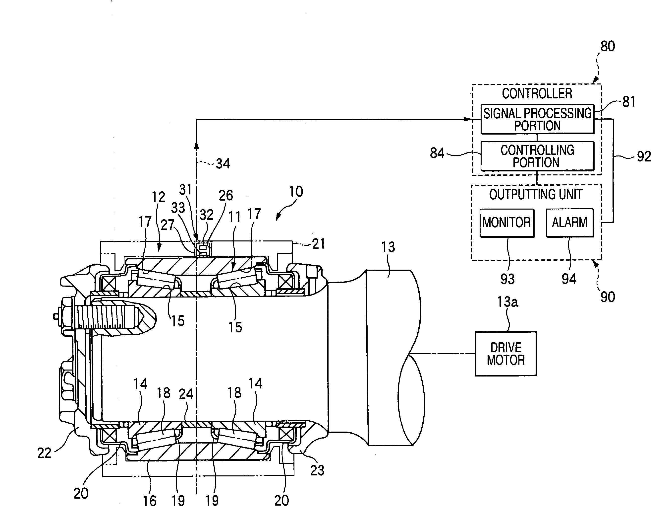
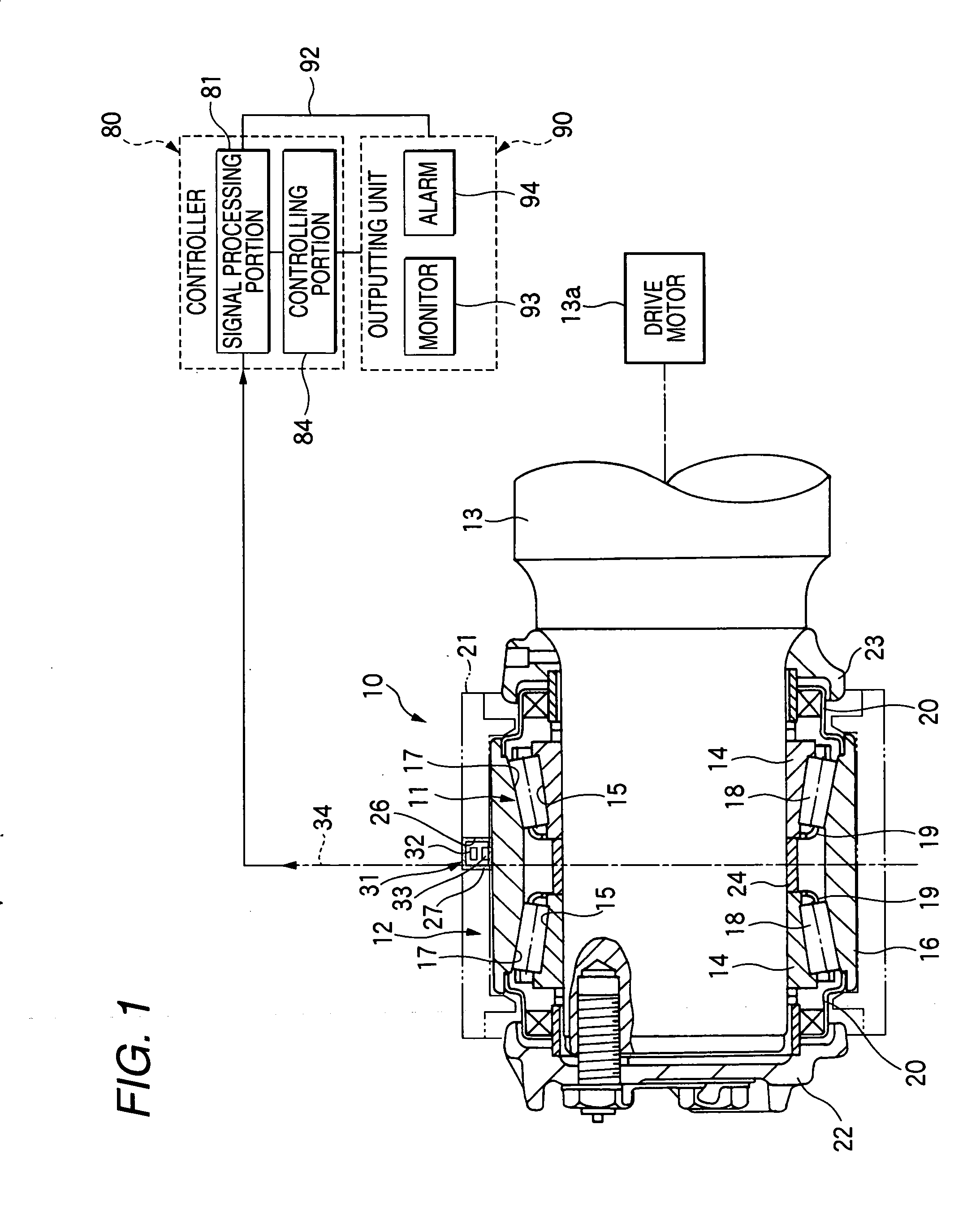
[0170]As shown by FIG. 1, the rolling bearing unit 10 for a railway vehicle including a machine equipment applied with a abnormality diagnosing apparatus includes: a double row tapered roller bearing 11 constituting a rotating part; and a bearing box 12 constituting a stationary member constituting a portion of a carriage for the railway vehicle. Further, the abnormality diagnosing apparatus includes: a detecting portion 31 for detecting a signal generated from the rolling bearing unit 10; a controller 80 including a signal processing portion 81 for determining a state of a abnormality or the like of the double row tapered roller bearing 11 from an electric signal outputted by the detecting portion 31; a controlling portion 84 for controlling to drive the roller bearing unit 10; and the outputting unit 90 of the monito...

second embodiment

[0196]Next, a abnormality diagnosing apparatus according to a second embodiment of the invention will be explained in details in reference to FIG. 7 and FIG. 8. Further, portions equivalent to those of the first embodiment are attached with the same notations and an explanation thereof will be omitted or simplified.

[0197]According to the embodiment, a state of rotating the double row tapered roller bearing 11 by inertia in a predetermined rotational speed zone when turning off the drive motor 13a (refer to FIG. 1) is detected by the signal processing portion 81 based on an OFF signal of the drive motor 13a, and the rotational speed sensor 40 and in the detecting, a abnormality of the double row tapered roller bearing 11 is diagnosed based on detecting signals by the vibration sensor 32 and the temperature sensor 33.

[0198]First, as shown by FIG. 7, the vibration signal generated by the vibration sensor 32, the temperature signal generated by the temperature sensor 33 are transmitted ...

third embodiment

[0207]Next, a abnormality diagnosing apparatus according to a third embodiment of the invention will be explained in reference to FIG. 9. Further, portions equivalent to those of the second embodiment are attached with the same notations and an explanation thereof will be omitted or simplified.

[0208]According to the abnormality diagnosing apparatus of the embodiment, as shown by a flowchart of FIG. 9, the rotational state determining portion 52 (refer to FIG. 7) determines whether information of the rotational speed of the double row tapered roller bearing 11 from the rotational speed sensor 40 falls in a zone of the rotational speed equal to or faster than 100 min−1 and equal to or slower than 1500 min−1 (step S21). Further, when information of the rotational speed of the double row tapered roller bearing 11 is outside of the zone of the rotational speed equal to or faster than 100 min−1 and equal to or slower than 1500 min−1, the operation returns to step S21 to repeat processing....


PUM


Abstract

A abnormality diagnosing apparatus used in a machine equipment including a rotating or sliding part relative to a stationary member includes a detecting portion 31 fixed to the rotating or sliding part or the stationary member and including a vibration sensor 32 and a temperature sensor 33, and a signal processing portion 81 for determining a state of the part from a detecting signal outputted by the detecting portion 31. The signal processing portion 81 determines presence or absence of a abnormality, or presence or absence of the abnormality and a degree of a damage of the part based on a combination of a measured result by the vibration sensor 32 and a measured result by the temperature sensor 33.

Description

TECHNICAL FIELD[0001]The present invention relates to a abnormality diagnosing apparatus and a abnormality diagnosing method of a rotating or a sliding part used in a machine equipment of, for example, an axle or a gear box of a railway vehicle or a reduction gear of a power generating windmill. Particularly, the present invention relates to a abnormality diagnosing apparatus and a abnormality diagnosing method of specifying presence or absence of the abnormality or a premonitory sign of the abnormality of the part, or a failed portion thereof.BACKGROUND ART[0002]Conventionally, in a rotating part of a railway vehicle, a power generating windmill or the like, after having been used for a constant period of time, presence or absence of a abnormality of damage, wear or the like is periodically inspected with regard to a bearing or other rotating part. The periodic inspection is carried out by disassembling a machine equipment integrated with the rotating part, and damage or wear broug...

Claims


Application Information

Patent Timeline
IPC IPC(8): G06F19/00G01M99/00
CPCF16C19/52G01H1/003F16C41/008G01M13/045G01M13/04F16C19/525F16C19/527F16C2233/00
Inventor MIYASAKA, TAKANORIMUTOH, YASUSHISAHARA, JUNTARO
Owner NSK LTD
Why Eureka
Try Eureka