Continuous flow sonic reactor

a sonic reactor and continuous flow technology, applied in mixers, heating fuel, applications, etc., can solve the problems of bursting of fluid, absorbing fluid, liberating heat, etc., and the usefulness of prior methods using ultrasound is believed to have been limited by the power of currently available ultrasound generators

Inactive Publication Date: 2008-10-02
GLOTOV VICTOR NIKOLAEVICH
View PDF10 Cites 23 Cited by
  • Summary
  • Abstract
  • Description
  • Claims
  • Application Information

AI Technical Summary

Benefits of technology

[0012]In summary, the present invention discloses a mechanical process involving the formation of cavitation bubbles in a feedstock and the subsequent collapse of the cavitation bubbles under sonic stress, e.g., with a sound wave. This straightforward method can be readily adapted to any fluid. The use of a modified centrifugal pump allows for the formation of the cavitation bubbles. The sonic s

Problems solved by technology

During the expansion cycle of an intensive ultrasound wave, the fluid is believed to be subjected to tensile stresses exceeding its ultimate strength, resulting in the bursting of the fluid.
During the compression cycle of the ultrasound wave, the bubble begins to collapse and the bubble walls rush at a high rate of acceleration towards the bubble center, thus compressing the vapor/gas mixture and causing peculiar reactions that liberate heat, which is absorbed by the fluid.
However, the usefulness of prior methods emp

Method used


Image

  • Continuous flow sonic reactor
  • Continuous flow sonic reactor
  • Continuous flow sonic reactor

Examples


Embodiment Construction

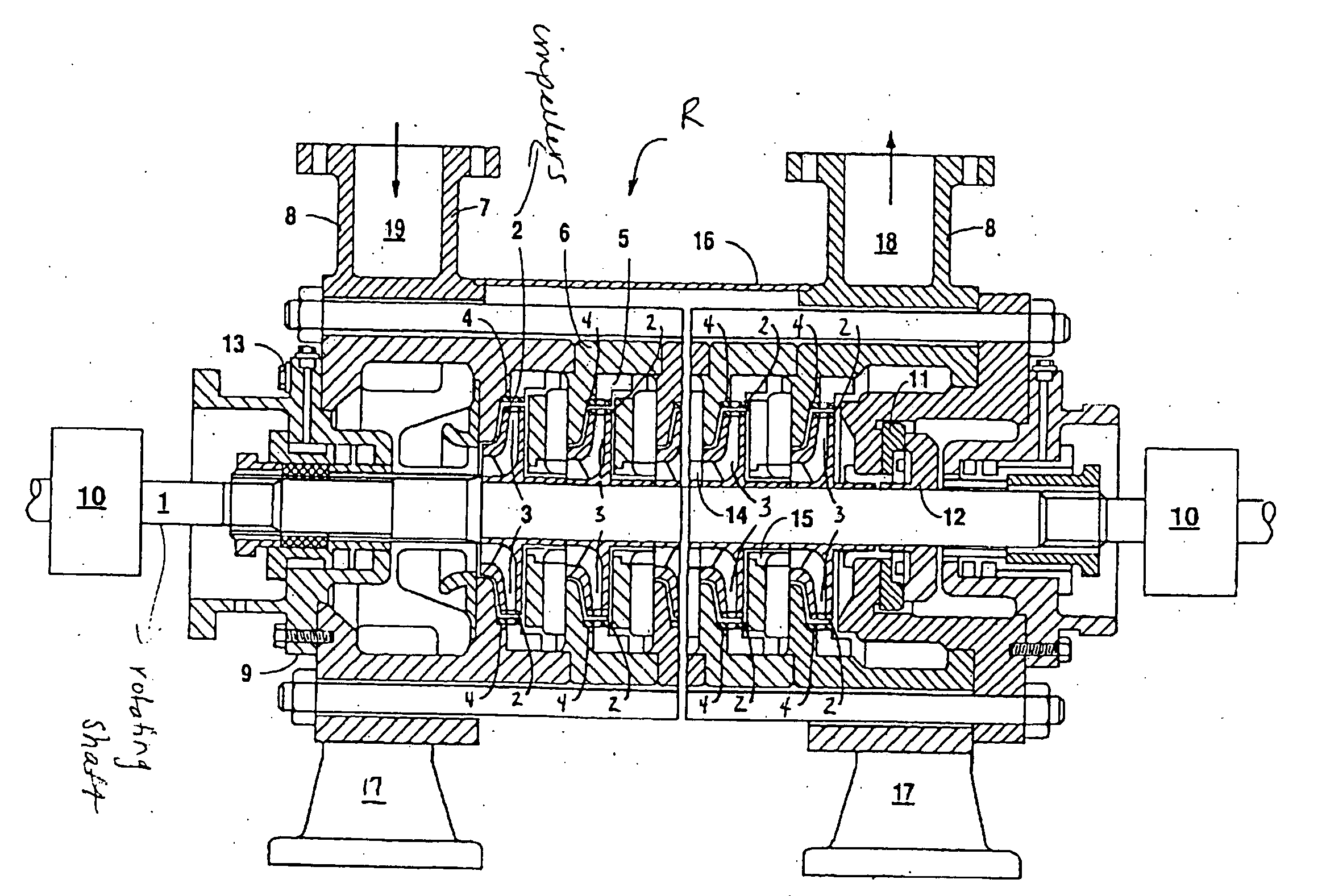
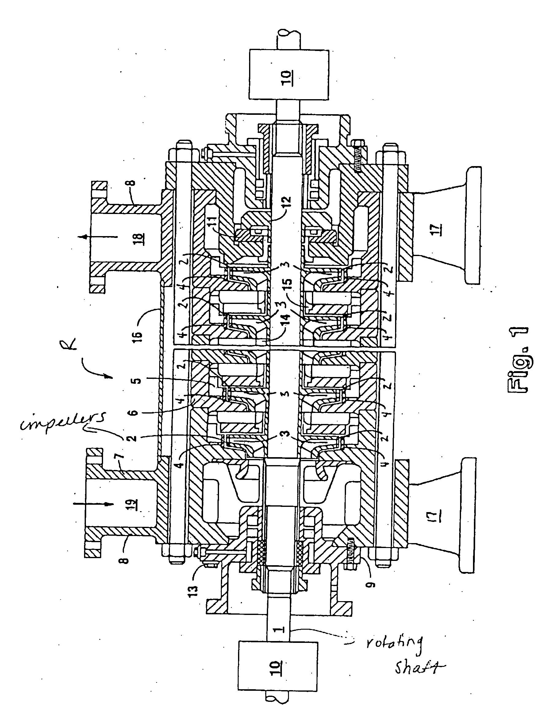
[0039]The reactor operates by moving the fluid on to the drive wheels rotating on one of several shafts. The fluid passes through a system of co-terminous and overlapping apertures of rotors and stators creating elastic fluctuations. The processing time is determined by the time it takes to pass through the working chambers of the reactor.

[0040]Referring now to the figures, FIG. 1 shows a cross-sectional view of a multistage centrifugal reactor R adapted to provide a high-intensity sound wave in a fluid feedstock. The rotating shaft 1 drives multiple rotors 3 mounted on the shaft. The fluid feedstock is propelled through apertures formed in impellers 2, which are rigidly mounted on the rotors, and nonrotating stators 4. Vaned or spiral-shaped volute diffusers 5 connect the outlet of each impeller to the inlet of the subsequent impeller. The rotors, impellers, stators and diffusers are installed in middle casings 6 and in two end casings 7 and 8. Also installed in the casings are sea...


PUM


Abstract

A centrifugal pump adapted to excite a high-intensity sound wave in a fluid feedstock is disclosed. The impeller and stator of the pump are provided with multiple apertures sized and spaced to produce a sound wave of an intensity greater than one megawatt per square meter in the fluid. The sound wave forms cavitation bubbles in the fluid, and the static pressure in the pump combines with the compression cycle of the sound wave to collapse the bubbles at a rate sufficient to cause exothermic reactions in the fluid. The sonic reactor can be configured for use to produce thermal energy, oil refining, catalyst production, water desalination and other uses.

Description

BACKGROUND OF THE INVENTION[0001]The present invention relates generally to the use of sound to create exothermic reactions in fluids, and in particular to the use of a centrifugal reactor adapted to create sonic energy to collapse cavitation bubbles in the fluid feedstock at a rate of speed sufficient to cause an exothermic reaction in the feedstock.[0002]It is known that chemical reactions can be created in a fluid by irradiating the fluid with ultrasonic energy of sufficient intensity to cause the formation and subsequent collapse of cavitation bubbles in the fluid. The chemical effects of ultrasound stem from the physical processes that apparently create, enlarge, and collapse bubbles of gaseous and vaporous cavities in a fluid. During the expansion cycle of an intensive ultrasound wave, the fluid is believed to be subjected to tensile stresses exceeding its ultimate strength, resulting in the bursting of the fluid. The resulting discontinuities, subjected to the action of surfa...

Claims


Application Information

Patent Timeline
IPC IPC(8): F01K25/00
CPCB01F5/162B01F7/00758B01F13/1013B01F13/1016B01J19/008B01J19/10B01J19/1806B01J19/1862B01J2219/0004B01J2219/0009F24V40/00F04D7/045B01F25/641B01F27/271B01F33/811B01F33/81
Inventor GLOTOV, VICTOR NIKOLAEVICH
Owner GLOTOV VICTOR NIKOLAEVICH
Why Eureka
Try Eureka