
Drive train for a motor vehicle and method for operating a drive train

a technology for driving trains and motor vehicles, applied in vehicle position/course/altitude control, process and machine control, instruments, etc., can solve the problems that the start-stop mode cannot be implemented and the internal combustion engine cannot be started by the first electrical machine, so as to increase the driving performance and reduce the fuel consumption of the internal combustion engine.

Inactive Publication Date: 2008-10-02
DAIMLER AG
View PDF1 Cites 28 Cited by
  • Summary
  • Abstract
  • Description
  • Claims
  • Application Information

AI Technical Summary

Benefits of technology

[0007]In a drive train for a motor vehicle with an internal combustion engine and a serial hybrid drive and a method for operating a motor vehicle with such a drive train, wherein the driving performance is increased and the fuel consumption of the internal combustion engine is reduced, and the drive shaft of the internal combustion engine is connected to a first electrical machine, and a second electrical machine is connected to a drive wheel of the motor vehicle, an electrical energy accumulator to which electrical energy can be supplied by the first and second first electrical machines and which can supply electrical energy to the first and second electrical machine is provided together with a control unit for dividing the power between the electrical energy accumulator and the first electrical machine, the rotational speed (n) of the first electrical machine and the power of the internal combustion engine are controlled depending on vehicle operating conditions and energy accumulator states selectively for high fuel efficiency or low emissions.
[0008]The first electrical machine can advantageously be operated in a highly dynamic, speed-controlled manner, making possible rapid adjustment of the rotational speed without assistance from the internal combustion engine. The rotational speed control of the first electrical machine also makes it possible to reliably limit of the rotational speed of the internal combustion engine in a coasting mode.
[0010]With the present invention, a start-stop mode can advantageously be implemented in a simple manner without structural switching in the control system solely by specifying a suitable control variable for controlling the rotational speed of the first electrical machine.
[0012]The power or torque command to the internal combustion engine is implemented directly via injection of the needed fuel quantity while avoiding transient (over-enriched) states, without high emission and consumption values during runup to speed. It also determines the steady-state power management and thus the charging and discharging of the energy accumulator. The advantageous steady-state operation of the internal combustion engine at the best point or on the best curve can be predetermined directly by specifying the rotational speed by means of the first electrical machine and the associated injection quantity, which is either controlled via a characteristic curve or, in order to increase accuracy, via a superposed power or torque control system. In two-point operation the internal combustion engine is operated either at the best point with highest efficiency or it is at a standstill, whereas with demand-controlled operation low loading on the energy accumulator is achieved together with good efficiency.
[0015]In a particular embodiment of the invention, a voltage limiting control system or a charge current limiting control system is connected to the input of the speed control system of the first electrical machine. In this way the limit values of the electrical energy accumulator can be respected sufficiently rapidly and the use of the mechanical friction brake can be reduced, because it is needed only when a power equilibrium can no longer be maintained over an extended period.

Problems solved by technology

If a rectifier, which is not capable of energy regeneration, is used in place of an inverter in a drive train, the internal combustion engine cannot be started by the first electrical machine.
A start-stop mode cannot therefore be implemented.

Method used


Image

  • Drive train for a motor vehicle and method for operating a drive train
  • Drive train for a motor vehicle and method for operating a drive train
  • Drive train for a motor vehicle and method for operating a drive train

Examples


Embodiment Construction

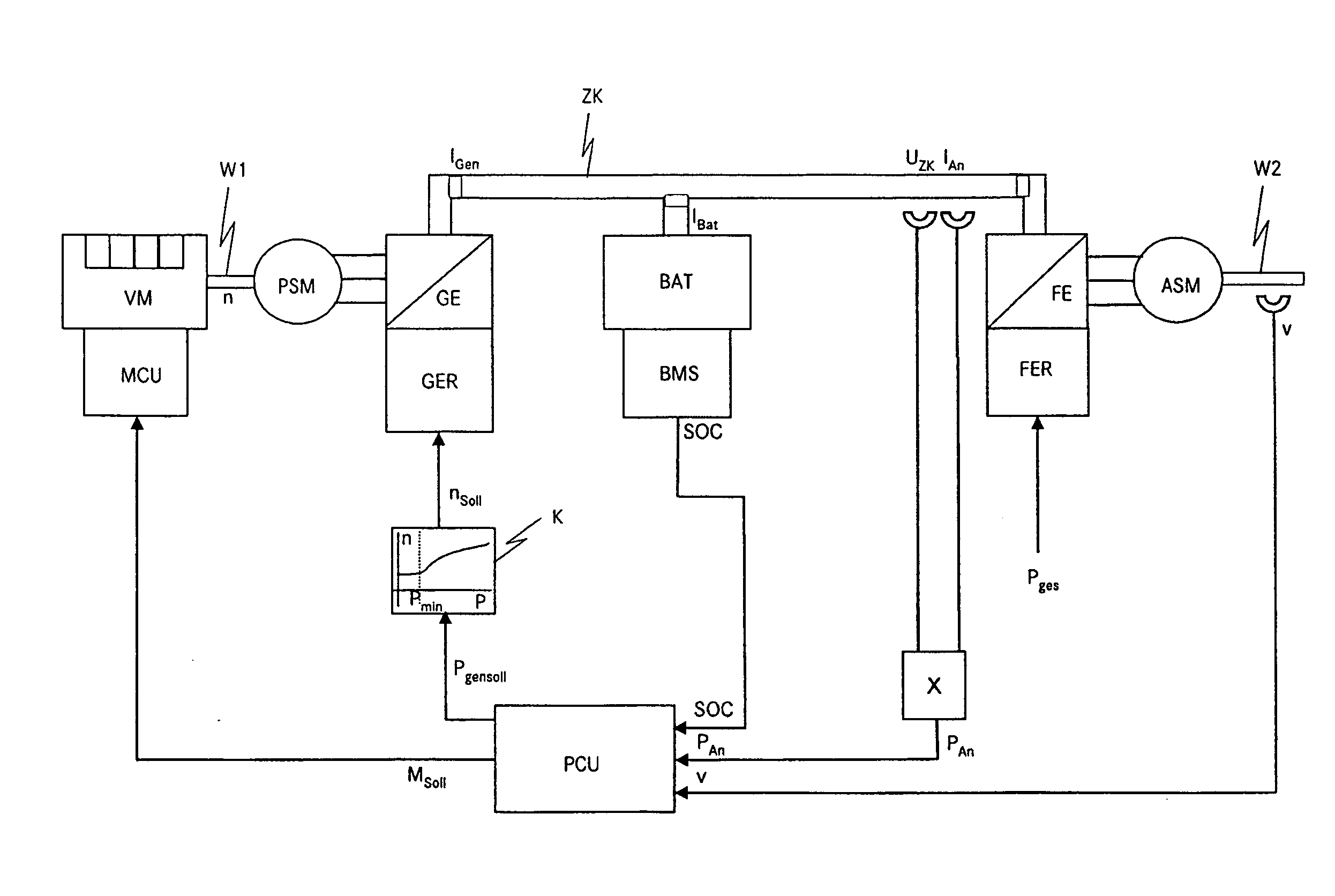
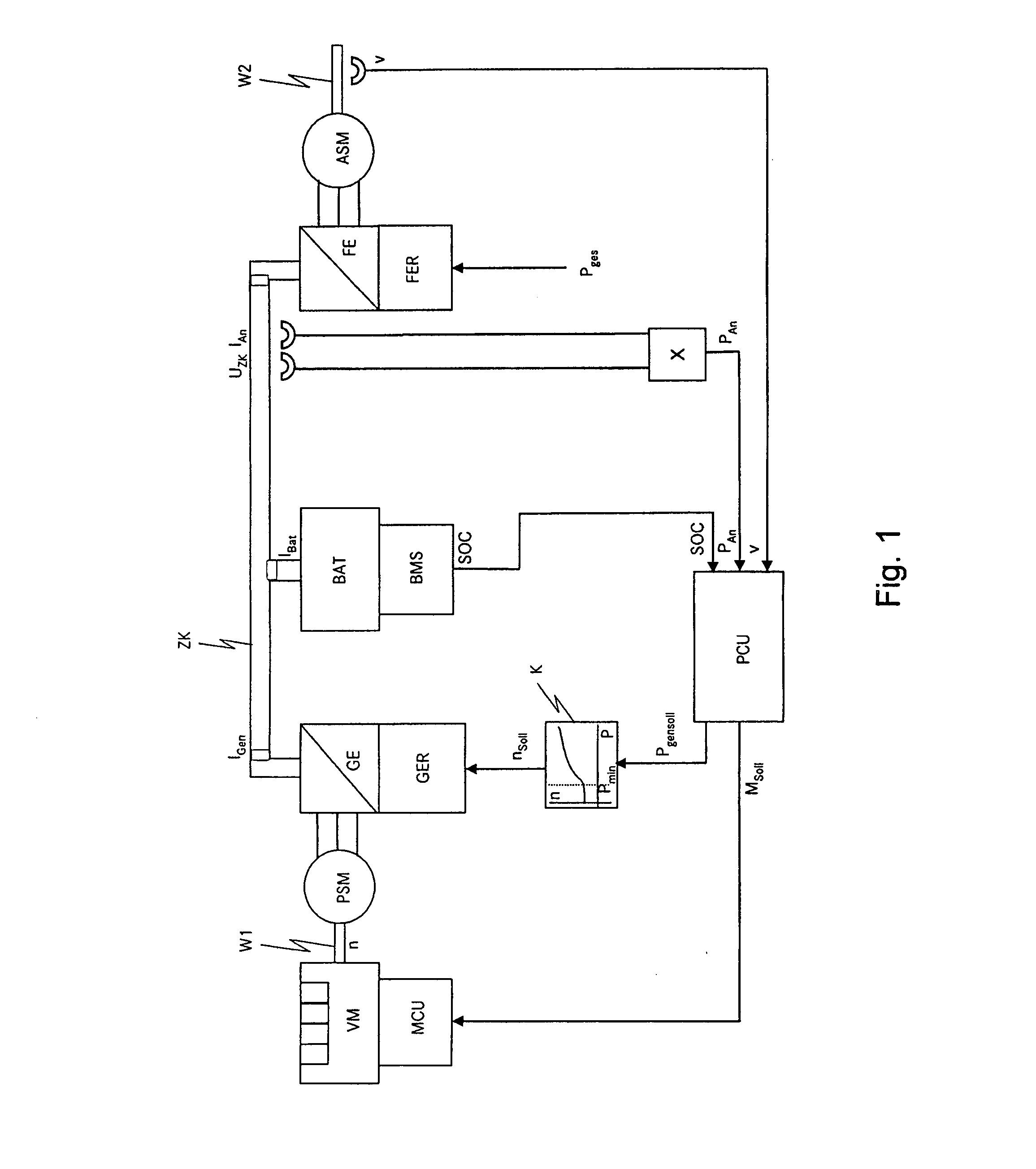
[0021]FIG. 1 shows an exemplary embodiment of a drive train according to the invention for a motor vehicle. In it the internal combustion engine VM is connected in a rotationally fixed manner via a drive shaft W1 to a first electrical machine PSM, preferably a permanently-excited synchronous machine. A second electrical machine ASM, preferably an asynchronous machine, is connected via a shaft W2 at least indirectly to a drive wheel (not shown). The second electrical machine ASM is preferably connected via the shaft W2 to an input shaft of a non-shiftable reduction gear. It is, however, also possible to connect the second electrical machine ASM mechanically to a transmission input shaft or transmission output shaft or directly to a driven axle or a wheel. It is also possible to provide a drive train according to the invention with a plurality of second electrical machines ASM.

[0022]The first electrical machine PSM is connected electrically via a first converter GE and the second elec...


PUM


Abstract

In a drive train for a motor vehicle with an internal combustion engine and a serial hybrid drive and a method for operating a motor vehicle with such a drive train, wherein the driving performance is increased and the fuel consumption of the internal combustion engine is reduced, and the drive shaft of the internal combustion engine is connected to a first electrical machine, and a second electrical machine is connected to a drive wheel of the motor vehicle, an electrical energy accumulator to which electrical energy can be supplied by the first and second first electrical machines and which can supply electrical energy to the first and second electrical machine is provided together with a control unit for dividing the power between the electrical energy accumulator and the first electrical machine, the rotational speed (n) of the first electrical machine and the power of the internal combustion engine are controlled depending on vehicle operating conditions and energy accumulator states selectively for high fuel efficiency or low emissions.

Description

[0001]This is a Continuation-in-Part Application of pending International patent application PCT / EP2006 / 006943 filed Jul. 15, 2006 and claiming the priority of German patent application 10 2005 037713.0 filed Aug. 10, 2005.BACKGROUND OF THE INVENTION[0002]The invention relates to a drive train for a motor vehicle with an internal combustion engine and a serial hybrid drive and also to a method for operating a drive train of a motor vehicle with an internal combustion engine and a serial hybrid drive.[0003]Motor vehicles with so-called serial hybrid drive are known. In these motor vehicles, during normal operation a first electrical machine is driven in a generating manner by an internal combustion engine and supplies electrical energy to an electrical energy accumulator, for example a traction battery. A second electrical machine fed by the electrical energy accumulator propels the motor vehicle via at least one driven wheel. In like manner, the second electrical machine may supply ...

Claims


Application Information

Patent Timeline
IPC IPC(8): B60K6/20B60L11/12H02P3/14B60K6/46B60L50/15
CPCB60K6/46B60L11/12B60W10/06B60W10/08B60W20/00B60W2510/244B60W2520/10Y02T10/6217Y02T10/6286Y02T10/7005Y02T10/7077B60L50/15Y02T10/62Y02T10/7072Y02T10/70B60W20/10
Inventor HELLER, MARCUSHENTSCHEL, FRANK
Owner DAIMLER AG
Learn More