
Optical filter

Inactive Publication Date: 2008-10-02
FUJIFILM CORP
View PDF4 Cites 14 Cited by
  • Summary
  • Abstract
  • Description
  • Claims
  • Application Information

AI Technical Summary

Benefits of technology

[0008]It is therefore an object of the present invention to provide an optical filter having a high reflectivity of reflection band.
[0027]The optical filter of the present invention is effective when incorporated in an image pickup device of an imaging system, especially such as a medical endoscope, for internal body observation and taking pictures of an internal body which is rich in red color component. The image pickup device equipped with the optical filter provides a high contrast of image of an affected area of an internal body and, in consequence, distinctiveness of the affected area. This feature facilitates observation of affected areas of an internal body when viewing them through endoscope having an image pickup device equipped with the optical filter.

Problems solved by technology

In addition, because the multilayer thin film looses a balance of stress due to a quite large ratio of physical thickness between the high and the low refraction index layer even though it may be realized to perform the precise control of physical thickness of the low refractive index layers, the multilayer thin film has a chance to encounter deterioration in its own mechanical and thermal durability.

Method used


Image

  • Optical filter
  • Optical filter
  • Optical filter

Examples


embodiment i

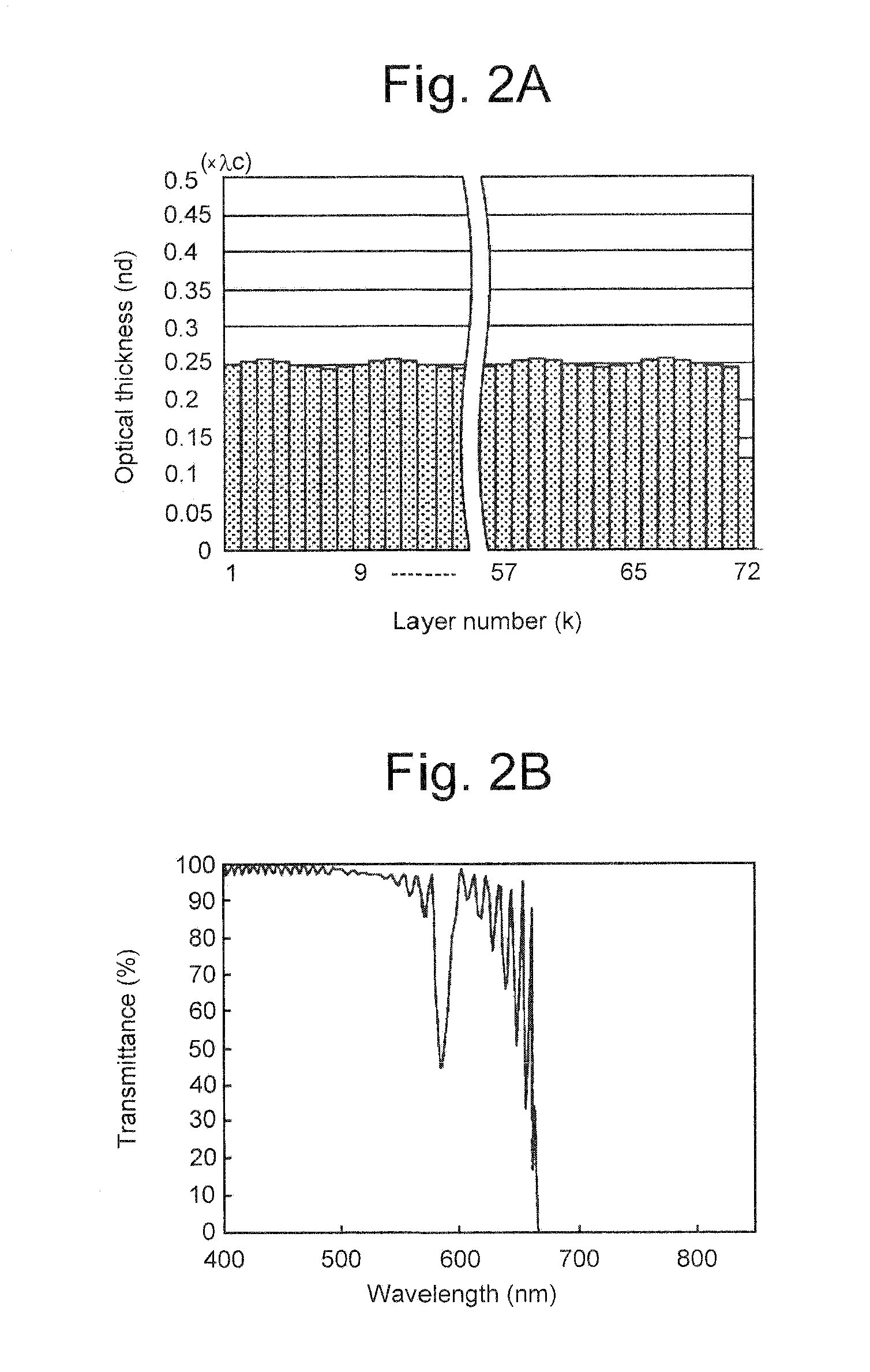
[0072]Six optical filters PEI-1 to PEI-6 were prepared as practical examples of the first embodiment, and one optical filter CEI-1 as a comparative example. Table I shows specific numerical data of the practical optical filters PEI-1 to PEI-6 and the comparative optical filter CEI-1. As shown in Table I, the individual optical filter, practical or comparative, was made up of nine layer-stacks identical with one another, each layer-stack consisting of eight alternative layers of high refractive index and low refractive index, and hence, made up of 72 layers in total and had a reflection band centered at a wavelength of 750 nm.

TABLE ICenterTotalwavelengthRatio of opticalRate ofPitch angleNumber ofnumber(.c nm)thickness (β)amplitude(a)(θ°)layer-stacksof layersCEI-17501045972PEI-175010.02545972PEI-275010.0545972PEI-375010.07545972PEI-475010.145972PEI-575010.245972PEI-675010.345972

[0073]As shown in Table I, the practical optical filters PEI-1 to PEI-6 were different only in the rate of a...

embodiment ii

[0076]Two optical filters PEII-1 and PEII-2 were prepared as practical examples of the second embodiment, and one optical filter CEII-1 as a comparative example. Table II shows specific numerical data of the respective optical filters PEII-1 to PEII-2 and CEII-1. As shown in Table II, the practical optical filters PEII-1 and PEII-2 of the second embodiment had the same specific numerical data as the practical optical filter PEI-2 of the previous embodiment, except for pitch angles (.) and the numbers of layer stacks. The comparative optical filter CEII-1 was similar to the practical optical filters PEII-1 and PEII-2 and, however, had a pitch angle of 0° which means that all of the layers have the same optical thickness (n×d=0.25.c). The practical optical filter PEII-1 was made up of six layer-stacks, each layer-stack consisting of 12 alternative layers of high refractive index and low refractive index, and hence, made up of 72 layers in total and the practical optical filter PEII-2 ...

embodiment iii

[0079]Three optical filters PEIII-1 to PEIII-3 were prepared as practical examples of the third embodiment. Table III shows specific numerical data of the respective practical optical filters PEIII-1 to PEIII-3. As shown in Table III, the practical optical filters PEIII-1 to PEIII-3 had the same specific numerical data as the practical optical filter PEI-2 of the first embodiment, except for the number of layer-stacks and the total number of layers, respectively. Specifically, the practical optical filter PEIII-1 to PEIII-3 were made up six, 12 and 15 layer-stacks, respectively, each of which consisted of the same number of, i.e. eight alternative layers of high refractive index and low refractive index, and consisted of 48, 96 and 150 layers in total, respectively.

TABLE IIICenterTotalwavelengthRatio of opticalRate ofPitch angleNumber ofnumber(.c nm)thickness (β)amplitude(a)(θ°)layer stacksof layersPEIII-175010.0545648PEIII-275010.05451296PEIII-375010.054515120

[0080]Investigation wa...


PUM


Abstract

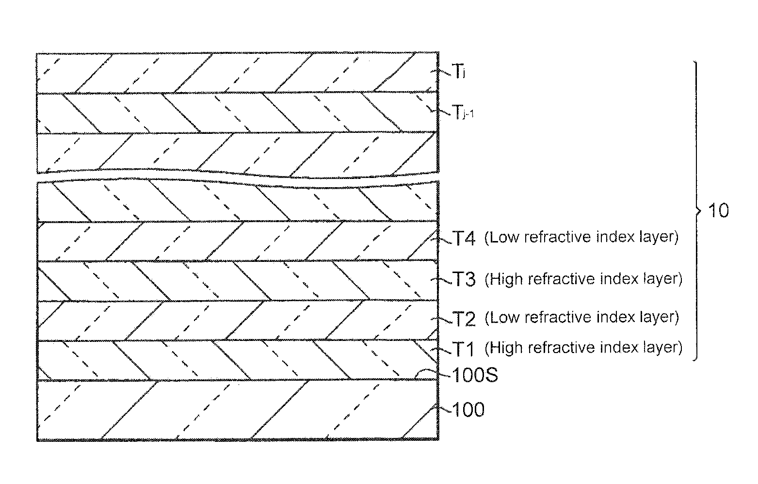
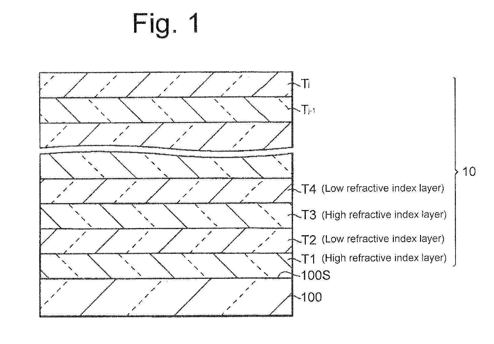
An optical filter has a multilayer thin film comprising first to i-th layers stacked in alternate layers of high and low refractive indices on a transparent substrate. Respective odd-numbered layers (Sigh refractive index layers) and respective even-numbered layers (low refractive index layers) form repetitive sequences of layers each of which cyclically changes in optical thickness throughout the multilayer tin film. Each of k-th from-the-bottom alternate layers of high and low refractive indices has such an optical thicknesses as meet the following conditional expressions (1) and (2), concurrently:n×d=(.c / 4)×[1+sin{(k−1)×}×.]  (1)0 . . . <1   (2)where.c is the center wavelength of reflection band,n is the ref ion index of the layer for the d-line,d is the physical thickness of the layer,. is a factor of a pitch angle represented by 2. / the number of layers a one layer-stack,. is the rate of amplitude.

Description

BACKGROUND OF THE INVENTION[0001]1. Field of the invention[0002]The present invention relates to an optical filter with a multilayer thin film comprising a plurality of layers stacked on a transparent substrate for attenuating light in a specified wavelength band.[0003]2. Description of Related Art[0004]There have been known optical filters having the optical properties that reflect light in a specified wavelength band centered at a reference wavelength and transmit light out of the specified wavelength band. One of these optical filters which has a high reflection band and high transmittance bands on opposite sides of the high reflection band is usually referred to as minus filter. Minus filters have multilayer film structures basically comprising alternate layers of high refractive index and low refractive index. In particular, such a minus filter as is capable of reflecting light in a relatively narrowband, such as several tens of nanometers, which is called a narrowband minus fi...

Claims


Application Information

Patent Timeline
IPC IPC(8): G02B1/10
CPCG02B5/285
Inventor AKIYA, SHUJI
Owner FUJIFILM CORP
Learn More