Knee Joint Prosthesis

a knee joint and prosthesis technology, applied in the field of knee joint prosthesis, can solve the problems of inability to move (hyperextension), lack of inherent stability of the knee joint, and decreased shallowness of the tibial plateau

Inactive Publication Date: 2008-10-02
SANCHETI KANTILAL HASTIMAL
View PDF7 Cites 126 Cited by
  • Summary
  • Abstract
  • Description
  • Claims
  • Application Information

AI Technical Summary

Benefits of technology

[0032]One object of the present invention is to provide a light weight k...

Problems solved by technology

Unlike the hip joint, the knee joint lacks inherent stability by virtue of bony articulations and depends upon soft tissue for its stability.
In addition, they decrease the shallowness of the tibial plateau.
Further movement (hyperextension) is not possible because the condyles of the femur abut against the tibial condyles.
While the knee generally serves its purpose very well, various disorders of the knee cause a great deal of pain and loss of mobility and function to those who are affected with such disorder.
Disorders can also result from sports injuries or accidents, contracted diseases, or more commonly due to “wear and tear”.
Arthritis affecting the knee often causes such pain and discomfort that older patients cannot maintain an independent lifestyle.
For example, malformation of joint surfaces can cause degeneration of joint, instability, deterioration of internal bone structures resulting in joint instability.
For this reason, such joints are considered to be undesirable, and may be prone to premature failure.
The knee prostheses of the first type also possess significant disadvantages in that they generally involve the removal of natural ligaments and only permit motion about a single axis as opposed to the controlled rotation and translation characteristic of a natural, healthy knee.
With...

Method used


Image

  • Knee Joint Prosthesis
  • Knee Joint Prosthesis
  • Knee Joint Prosthesis

Examples


case 1

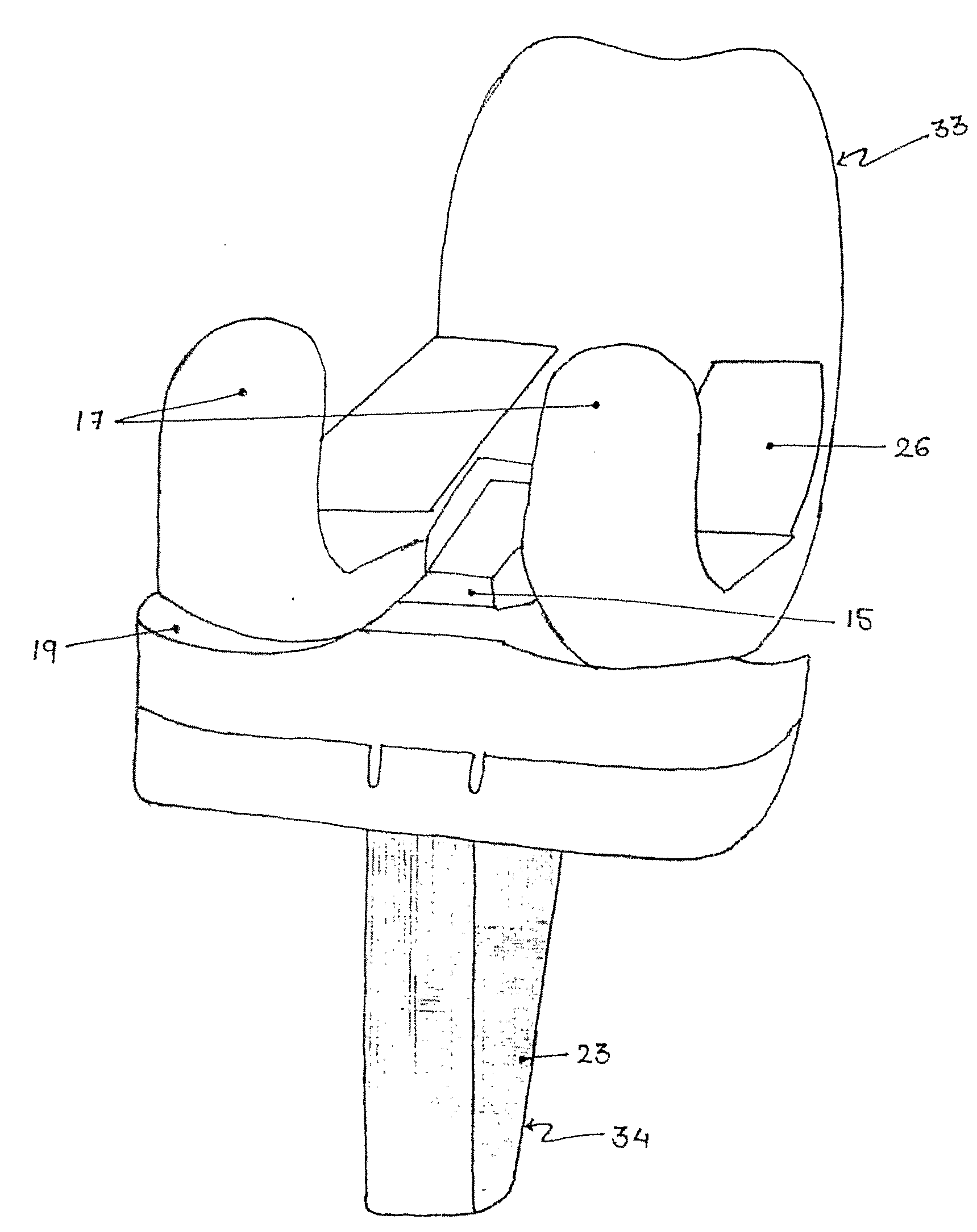
[0118]A 58 year old female patient presented herself with severe pain in the right knee an inability to carry activities of daily living with deformity in her right knee, Patient had undergone total knee replacement surgery for her left knee using conventional indigenous knee prosthesis. The right knee was operated for TKR using the prosthesis of this invention. The surgical procedure was performed under spinal and epidural anesthesia in supine position using tourniquet and side and distal posts. An anterior midline incision was taken. Medial capsulotomy was performed after capsular marking using a sharp scalpel. The Patella was everted and locked in the everted position and resurfaced. The femoral and tibial osteophytes were removed to obtain a better anatomical shape of the femoral and tibial condyles. Medial peritibial release was done for ligament balancing. Femoral and tibial cuts were taken followed by sizing for the prosthetic components. Medium plus femoral component and med...


PUM


Abstract

A knee joint prosthesis is disclosed. The prosthesis has a femoral component and a tibial component. The tibial component has a tibial plateau element fitted in a tibial tray element. A hemi capstan shaped bridge member is provided between replicated condyles on the femoral component. A specially shaped post is provided between kidney shaped meniscal depression on the tibial plateau element. The bridge member and the post act together to form an additional joint for load transfer during deep flexion of the prosthesis in its operative configuration.

Description

FIELD OF INVENTION[0001]This invention relates to knee joint prosthesis.[0002]Particularly the present invention relates to a knee joint prosthesis having a greater degree of knee flexion.[0003]More particularly the invention relates to a knee joint prosthesis, which replaces the articulating surfaces of the femur and the tibia.DESCRIPTION OF THE PRIOR ARTIntroduction:[0004]The human knee joint (60) as seen in FIGS. 1, 2 and 3 of the accompanying drawings, serves an essential function to allow individuals to lead a normal life. It is the largest and one of the most structurally complicated joint in the human body and a major joint for locomotion. This is due to the fact that it is the site of articulation of the longest levers of the lower limb (the femur and leg bones), which are characterized by the largest range of movements made in walking. Unlike the hip joint, the knee joint lacks inherent stability by virtue of bony articulations and depends upon soft tissue for its stability...

Claims


Application Information

Patent Timeline
IPC IPC(8): A61F2/38
CPCA61F2/3877A61F2/3886A61F2310/00029
Inventor SANCHETI, KANTILAL HASTIMAL
Owner SANCHETI KANTILAL HASTIMAL
Why Eureka
Try Eureka