Printing method, printing apparatus and liquid-crystal display device using the same

Inactive Publication Date: 2008-10-09
NEC LCD TECH CORP
View PDF0 Cites 20 Cited by
  • Summary
  • Abstract
  • Description
  • Claims
  • Application Information

AI Technical Summary

Benefits of technology

[0067]With the LCD device according to the third aspect of the invention, since at least one of the pair of transparent substrates comprises the ink pattern printed by the printing method according to the first aspect of the invention, the said ink pattern is p

Problems solved by technology

However, in recent years, to lower the fabrication cost of the LCD device furthermore, the use of a printing method has been researched and proposed as the substitute technique for the photolithography method that necessitates complicated processes and costly fabrication apparatuses.
However, the above-described prior-art printing apparatuses have the problems explained below.
As a result, a problem that the reproducibility of the said ink pattern degrades will arise.
Moreover, since the ink pattern, which will be transferred to the flat substrate 105, is formed on the cylindrical blanket 102, sufficient alignment is unable to be performed prior to t

Method used


Image

  • Printing method, printing apparatus and liquid-crystal display device using the same
  • Printing method, printing apparatus and liquid-crystal display device using the same
  • Printing method, printing apparatus and liquid-crystal display device using the same

Examples


first embodiment

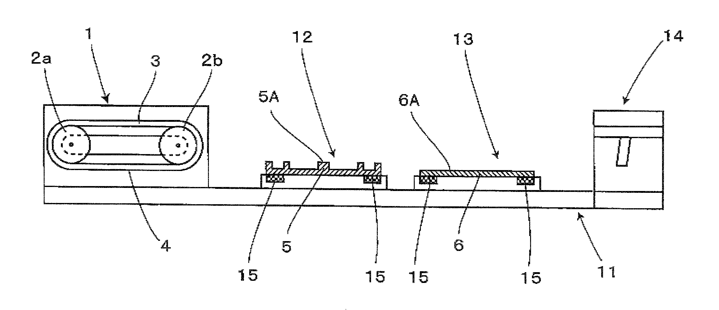
[0100]A transfer system or mechanism 1 of a printing apparatus used in a printing method according to a first embodiment of the invention is shown in FIGS. 5 to 7. FIG. 5 shows the structure of the transfer system 1 and FIGS. 6 and 7 show the structure of the printing apparatus.

[0101]As shown in FIG. 5, a transfer system 1 comprises a pair of printing rollers 2a and 2b, and a blanket 3 placed to surround the rollers 2a and 2b. The side shape of the transfer system 1 is approximately elliptic. Concretely speaking, the two cylindrical printing rollers 2a and 2b are disposed apart from each other at a predetermined distance in such away as to be approximately parallel to the printing direction P. The endless belt-shaped blanket 3 is put around the rollers 2a and 2b. A lower one of the two horizontally extending portions of the blanket 3 between the rollers 2a and 2b forms a flat portion 4 to be used for the formation and transfer of an ink pattern.

[0102]Here, the diameters of the two r...

second embodiment

[0163]FIG. 19 is an explanatory side view showing the schematic structure of a transfer system 1A incorporated into a printing apparatus according to a second embodiment of the invention. FIG. 20 is an explanatory side view showing the schematic structure of the transfer system 1A, where a blanket drying system or mechanism 33 is added.

[0164]As shown in FIG. 19, the transfer system 1A according to the second embodiment comprises a blanket roller 32 in addition to the pair of printing rollers 2a and 2b. The rollers 2a and 2b and the blanket roller 32 are arranged at the three apices of a triangle, respectively. The endless belt-shaped blanket 3 is put around the printing rollers 2a and 2b and the blanket roller 32. Such the structure gives an advantage that the area or size of the blanket 3 provided in the transfer system 1A is enlarged compared with the aforementioned first embodiment.

[0165]With the second embodiment, one blanket roller 32 is provided; however, two or more blanket r...

third embodiment

[0172]FIG. 21 shows a printing apparatus according to a third embodiment of the invention. This apparatus has a structure corresponding to the combination of a printing plate exchange system 41 and the structure of the above-described printing apparatus according to the first embodiment. With the printing apparatus of the third embodiment, the printing plate 5 fixed to the printing plate stage 12 can be automatically exchanged for another printing plate during the printing operation.

[0173]The printing plate exchange system 41 comprises a printing plate stock section 42 and a printing plate transport system 43, as shown in FIG. 21. The printing plate stock section 42 stocks a plurality of kinds of the printing plates 5. The printing plate transport system 43 selects one of the printing plates 5 stocked in the printing plate stock section 42, and transports the printing plate 5 thus selected to the printing plate stage 12. Moreover, the printing plate transport system 43 takes the pri...


PUM


Abstract

A printing method realizes good reproducibility of an ink pattern and facilitates both the alignment operation between a printing plate and a blanket and the alignment operation between the blanket and a substrate, enabling the printing with positional accuracy as high as the TFT substrate can be fabricated. The flat portion of the printing plate and the flat portion of the endless belt-shaped blanket are contacted in the state where the said flat portions are opposed. Then, the said flat portions are detached, forming an ink pattern on the flat portion of the blanket. Thereafter, the flat portion of the blanket and the flat portion of the substrate are contacted in the state where the said flat portions are opposed. Subsequently, the said flat portions are detached, transferring the ink pattern to the flat portion of the substrate from the blanket.

Description

BACKGROUND OF THE INVENTION[0001]1. Field of the Invention[0002]The present invention relates to a printing method, a printing apparatus, and a Liquid-Crystal Display (LCD) device and more particularly, to a printing method and a printing apparatus for forming an ink pattern on a blanket using a printing plate and for transferring the ink pattern to a substrate from the blanket, and a LCD device fabricated by using the printing method.[0003]In this specification, the term “blanket” means a member or structural component on the surface of which an ink pattern is temporarily formed using a printing plate, and which is used for transferring the ink pattern thus formed to a target object. Typically, a “blanket” is produced by covering the surface of an elastic base cloth with an elastic material, such as a rubber.[0004]2. Description of the Related Art[0005]In recent years, the LCD device has been extensively used as a high-resolution display device. The LCD device comprises a transpare...

Claims


Application Information

Patent Timeline
IPC IPC(8): B41F7/02
CPCB41F17/007B41M3/00H01L27/1292G02F1/133514H01L51/0004G02F1/133371H10K71/13
Inventor TAKAMATSU, HIDEAKI
Owner NEC LCD TECH CORP
Why Eureka
Try Eureka