Motor driving circuit

a technology of motor driving and circuit, which is applied in the direction of process and machine control, electronic commutators, instruments, etc., can solve the problems of increasing the circuit size of digital filters, and achieve the effect of suppressing the increase in the circuit size and enhancing the starting characteristi

Active Publication Date: 2008-10-09
ROHM CO LTD
View PDF4 Cites 7 Cited by
  • Summary
  • Abstract
  • Description
  • Claims
  • Application Information

AI Technical Summary

Benefits of technology

[0007]The present invention is accomplished in view of the above-mentioned problem, and a general purpose thereof is to provide a motor driving technique that suppresses the increase in the circuit size and has enhanced starting characteristic.

Problems solved by technology

Specifically, as the sampling frequency of the error signal is high, the characteristic of the digital filter is improved, thereby providing an advantage that the transient response, e.g., the starting characteristic of the motor can be improved, but causing a problem that the circuit size of the digital filter increases.

Method used


Image

  • Motor driving circuit
  • Motor driving circuit
  • Motor driving circuit

Examples


first embodiment

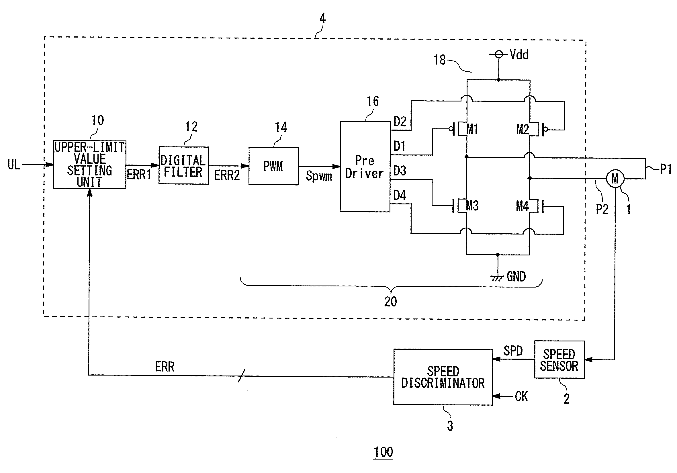
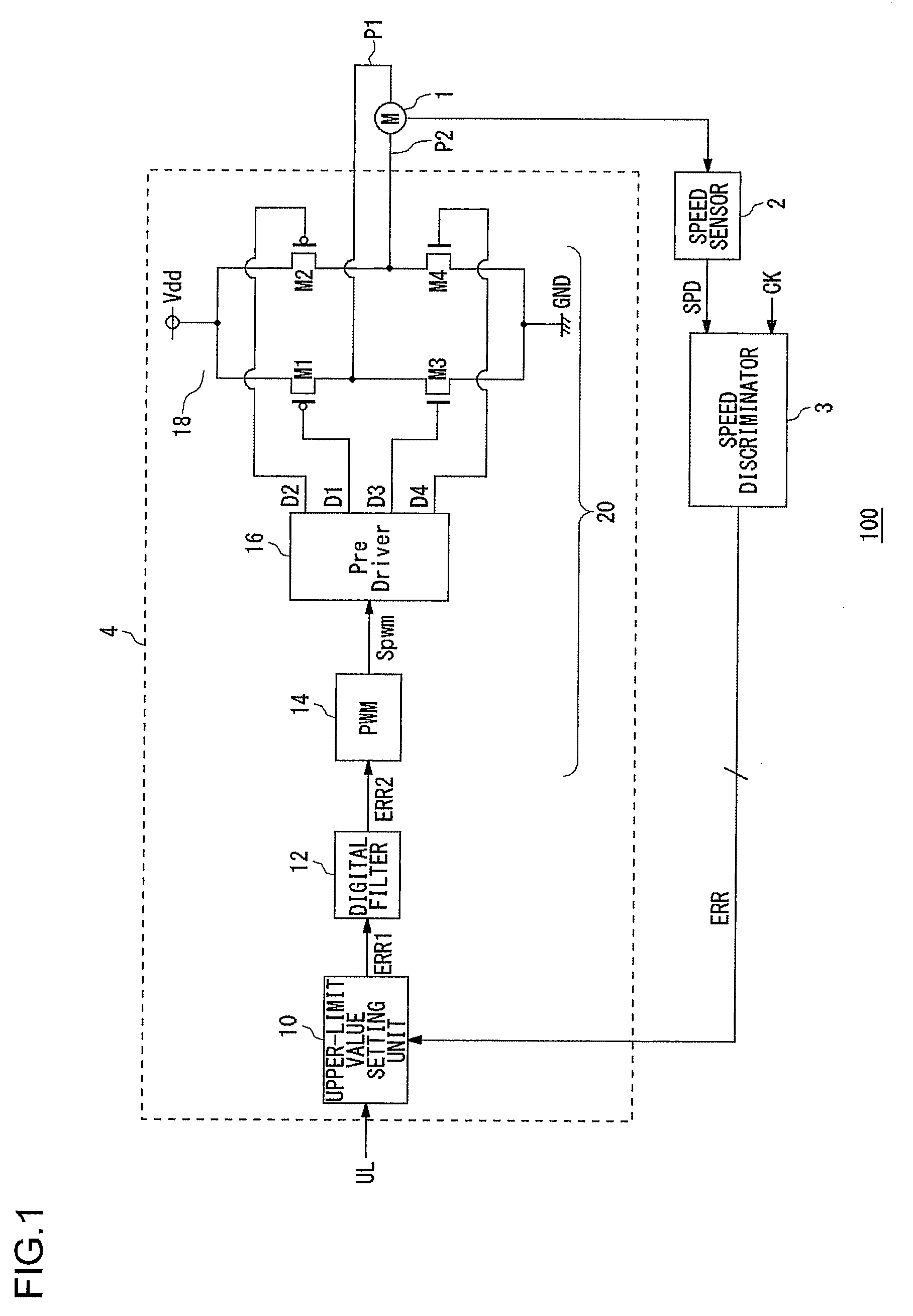
[0028]FIG. 1 is a block diagram showing a configuration of a motor driving apparatus 100 according to a first embodiment. FIG. 1 shows a motor 1, which a subject to be driven, together with the motor driving apparatus 100. The motor 1 and the motor driving apparatus 100 are mounted to an electronic apparatus having a movable unit. The motor 1 is connected to the movable unit of the electronic apparatus. The rotation speed of the motor 1 is controlled by the motor driving apparatus 100, whereby the motor 1 drives the movable unit. For example, the electronic apparatuses include a digital still camera or digital video camera, wherein the motor 1 is utilized for moving a lens or shutter.

[0029]The motor driving apparatus 100 drives the motor in such a manner that the rotation speed thereof approaches a desired target value, while monitoring the rotation speed of the motor 1. The motor driving apparatus 100 has a speed sensor 2, speed discriminator 3, and motor driving circuit 4.

[0030]Th...

second embodiment

[0051]In the motor driving apparatus 100 according to the above-mentioned first embodiment, the upper-limit value setting unit 10 is provided to set the upper limit value to the error signal ERR, whereby the prevention of the overshoot and the shortening of the starting time can be realized. The motor driving apparatus 100 according to the second embodiment has a feature in the digital filter 12, and the other configurations are the same as those of the motor driving apparatus 100 according to the first embodiment shown in the block diagram of FIG. 1.

[0052]FIGS. 3A and 3B are circuit diagrams showing the configuration of the digital filter 12 in the motor driving apparatus 100 according to the second embodiment. FIG. 3A is a diagram showing the configuration of the digital filter 12, and FIG. 3B shows the configuration of an analog filter that is equivalent to FIG. 3A.

[0053]An analog filter 12′ in FIG. 3B is a low-pass filter including capacitors C1 and C2 and resistor R1. The trans...


PUM


Abstract

A motor driving circuit drives a motor on receipt of an error signal having a digital value corresponding to a deviation between a current rotation speed of the motor, which is the subject to be driven, and its target value. A digital filter eliminates a high-frequency component of the error signal. A driving unit controls an electric current flowing through the motor in accordance with the digital value of the error signal from which the high-frequency component is eliminated by the digital filter. An upper-limit value setting unit sets an upper limit value to the digital value of the error signal input to the digital filter. The upper-limit value setting unit is configured to be capable of changing the upper limit value in accordance with a setting signal from the outside.

Description

BACKGROUND OF THE INVENTION[0001]1. Field of the Invention[0002]The present invention relates to a motor driving technique, and more particularly to a control technique of a rotation speed (frequency) of a motor.[0003]2. Description of the Related Art[0004]A motor driving apparatus that drives a DC (direct current) motor or a spindle motor with a desired rotation speed monitors the rotation speed of the motor so as to produce a driving signal on the basis of the deviation from a desired target value. The motor driving apparatus that controls a motor as described above may employ a speed discriminator disclosed in the Japanese Patent Application (Laid-Open) No. H06-30589, for example.[0005]Some of the speed discriminators compare a current rotation speed of the motor and a rotation speed that is a desired target value, and outputs an error signal according to the deviation as a digital value. This error signal produces a pulse-width modulation signal having a duty ratio according to ...

Claims


Application Information

Patent Timeline
Patent Type & Authority Applications(United States)
IPC IPC(8): H02P7/29H02P29/00
CPCH02P6/165H02P6/17
Inventor SUGIE, HISASHI
Owner ROHM CO LTD
Why Eureka
Try Eureka