Production Method for Sold Polymer Electrolyte Membrane, Solid Polymer Electrolyte Membrane, and Fuel Cell Including Solid Polymer Electrolyte Membrane

a technology of electrolyte membrane and sold polymer, which is applied in the direction of final product manufacture, sustainable manufacturing/processing, electric/magnetic/electromagnetic heating, etc., can solve the problems of inability to meet the needs of customers, etc., to suppress the swelling of the membrane surface direction, improve the effect of electric power generation efficiency, and suppress the deterioration of the electrolyte membran

Inactive Publication Date: 2008-10-09
TOYOTA JIDOSHA KK
View PDF2 Cites 27 Cited by
  • Summary
  • Abstract
  • Description
  • Claims
  • Application Information

AI Technical Summary

Benefits of technology

[0023]With such a fuel cell, it is possible to improve the electric power generation efficiency by applying a strong magnetic field to the polymer contained in the solid polymer electrolyte membrane such that the ion-conductivity become relatively high in the membrane thickness direction. Also, it is possible to suppress deterioration of the electrolyte membrane by applying a strong magnetic field to the polymer such that swelling in the membrane surface direction is suppressed.

Problems solved by technology

However, a fluorinated electrolyte membrane is difficult to produce, and considerably costly.
However, it is not always desirable that the electrolyte membrane has physical properties of swelling isotropically and having isotropic ion conductivity.
Nevertheless, a close study has not been made concerning this issue.

Method used


Image

  • Production Method for Sold Polymer Electrolyte Membrane, Solid Polymer Electrolyte Membrane, and Fuel Cell Including Solid Polymer Electrolyte Membrane
  • Production Method for Sold Polymer Electrolyte Membrane, Solid Polymer Electrolyte Membrane, and Fuel Cell Including Solid Polymer Electrolyte Membrane
  • Production Method for Sold Polymer Electrolyte Membrane, Solid Polymer Electrolyte Membrane, and Fuel Cell Including Solid Polymer Electrolyte Membrane

Examples


Embodiment Construction

[0030]In the following description, the present invention will be described in more detail in terms of exemplary embodiments.

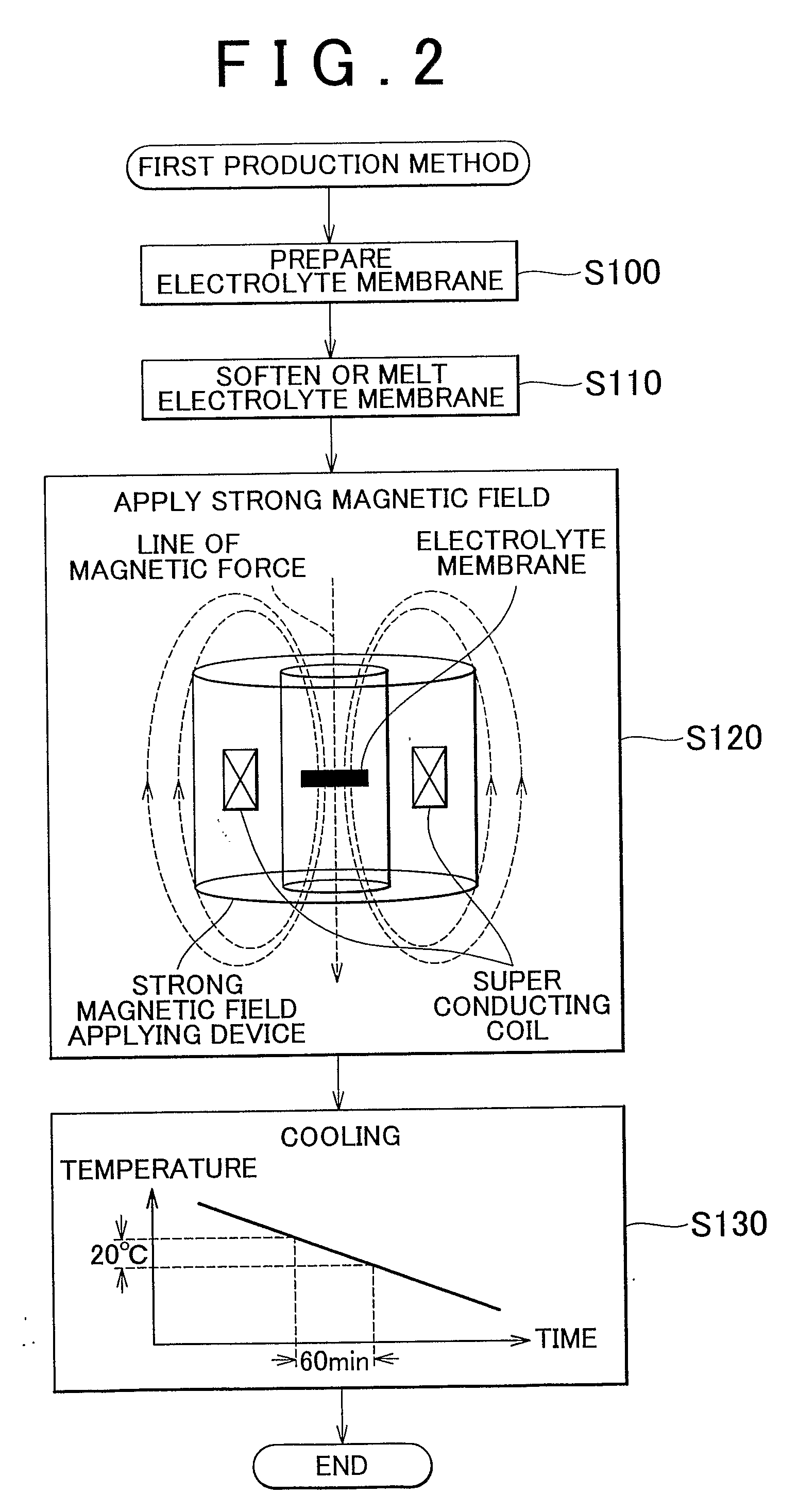
[0031]A structure of a fuel cell will be schematically described. According to the invention, polymers contained in a solid polymer electrolyte membrane (hereinafter, simply referred to as an “electrolyte membrane”) are oriented in a certain direction in strong magnetic fields. First, a structure of a polymer electrolyte fuel cell including this electrolyte membrane will be briefly described.

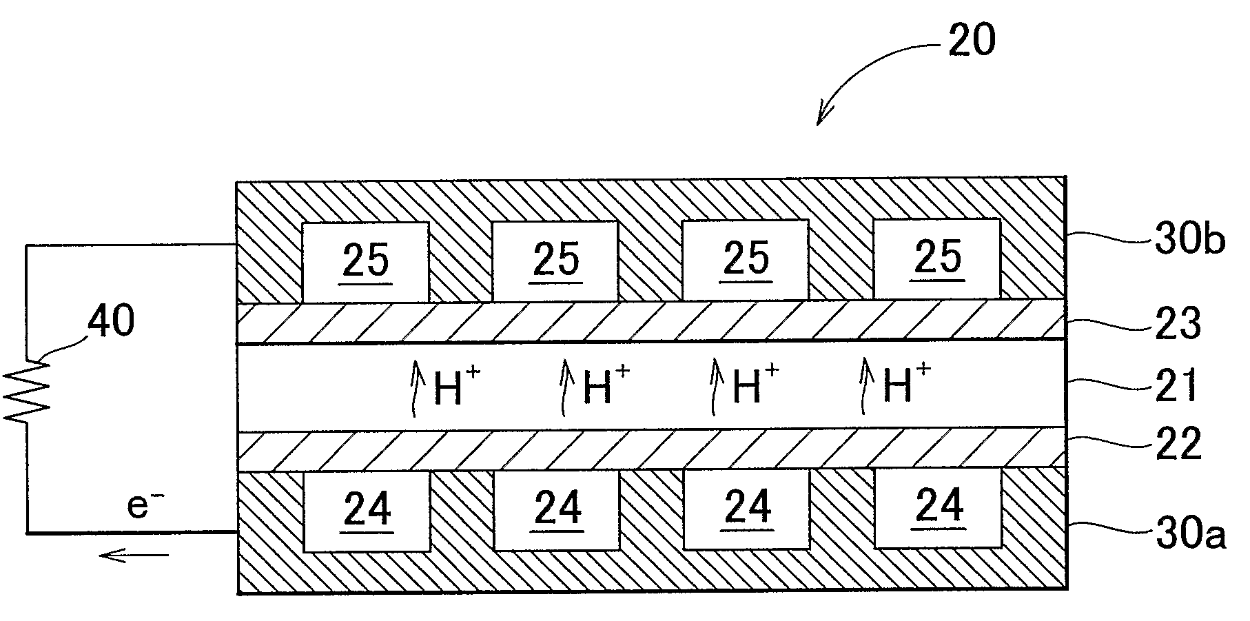
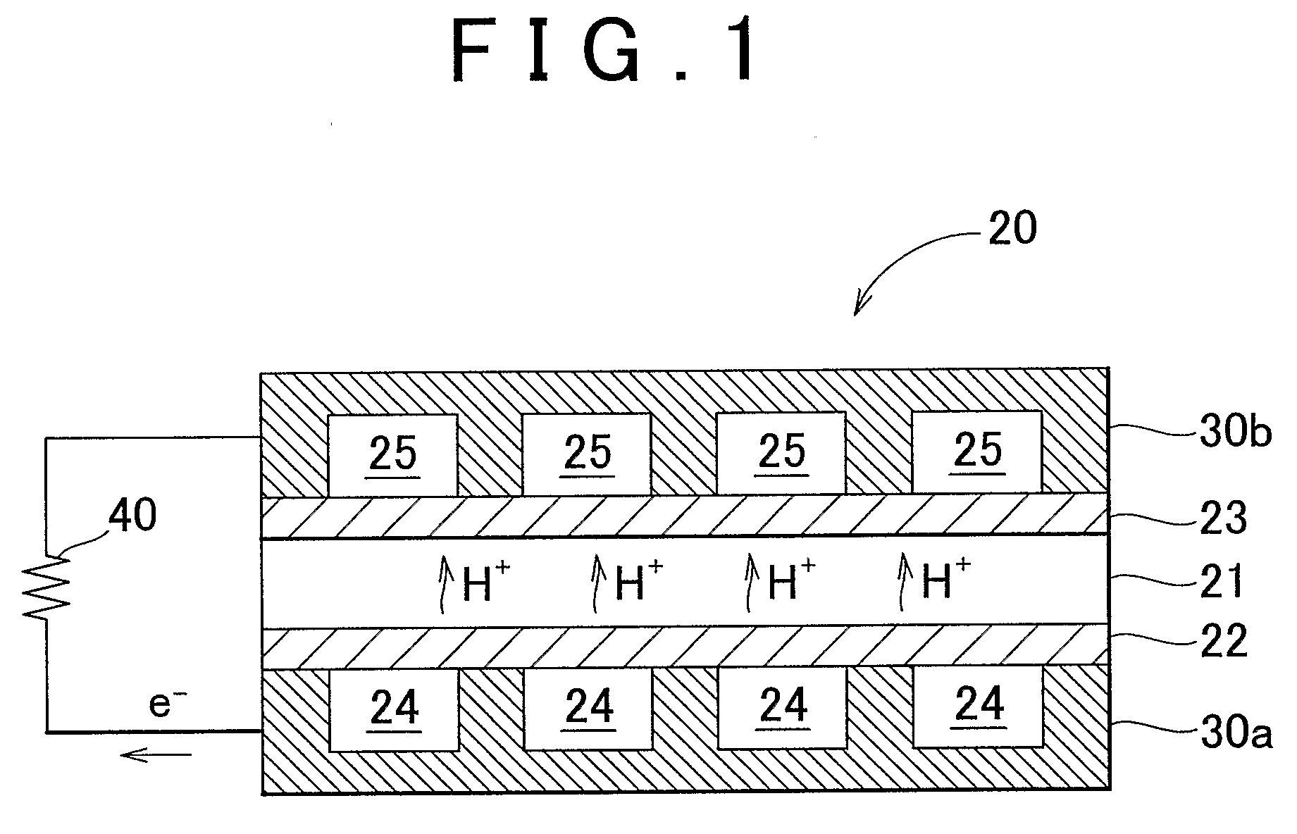
[0032]FIG. 1 is a cross sectional view showing a cell 20 which includes an electrolyte membrane 21 according to an embodiment of the invention, and which is a structural unit of a fuel cell. As shown in FIG. 1, the cell 20 includes the electrolyte membrane 21; an anode 22 and a cathode 23 which makes a pair and which sandwich the electrolyte membrane 21 such that a sandwich structure is formed; and separators 30a and 30b which sandwich the sandwich structure. Fuel gas pass...


PUM

PropertyMeasurementUnit
physical propertiesaaaaaaaaaa
magnetic fieldaaaaaaaaaa
strengthaaaaaaaaaa

Abstract

The performance of an electrolyte membrane (21) is improved by imparting aeolotropy to physical properties of the electrolyte membrane (21). A first state solid polymer electrolyte membrane (21) containing a polymer having an ion-exchange group is softened, melted of dissolved, whereby a second state solid polymer electrolyte membrane (21) is formed. Then, the second state solid polymer electrolyte membrane (21) is cooled, while a strong magnetic field is applied to the second state solid polymer electrolyte membrane (21) in a predetermined direction, whereby the second state solid polymer electrolyte membrane (21) is hardened or solidified. As a result, the ion-conductivity in a membrane thickness direction can be improved in a fluorinated electrolyte membrane, and swelling in the membrane surface direction can be suppressed in an aromatic hydrocarbon electrolyte membrane.

Description

BACKGROUND OF THE INVENTION[0001]1. Field of the Invention[0002]The invention relates to a solid polymer electrolyte membrane having ion-conductivity, a production method for the solid polymer electrolyte membrane, and a fuel cell including the solid polymer electrolyte membrane.[0003]2. Description of the Related Art[0004]Recently, attention has been focused on a fuel cell which generates electric power by using an electrochemical reaction between hydrogen and oxygen, as a supply source of clean electric energy. Especially, great expectations have been placed on a polymer electrolyte fuel cell (PEFC) which uses a solid polymer as an electrolyte, since the PEFC can generate a large amount of electric power and operate at a low temperature.[0005]As an electrolyte membrane used for a fuel cell, generally, a fluorinated electrolyte membrane typified by a perfluoro sulfonic acid membrane is used. The fluorinated electrolyte membrane has C—F bond, and has considerably high chemical stabi...

Claims


Application Information

Patent Timeline
Patent Type & Authority Applications(United States)
IPC IPC(8): H01M8/10C08J5/22
CPCB29C67/02B29L2031/3468C08J5/2243C08J5/2275H01M8/1004H01M8/1023H01M8/1025H01M8/1027H01M8/1032H01M8/1039H01M8/1081H01M8/1086Y02E60/521C08J2353/02Y02E60/50Y02P70/50
Inventor KIMURA, HIROKOSEKINE, SHINOBU
Owner TOYOTA JIDOSHA KK
Why Eureka
Try Eureka